
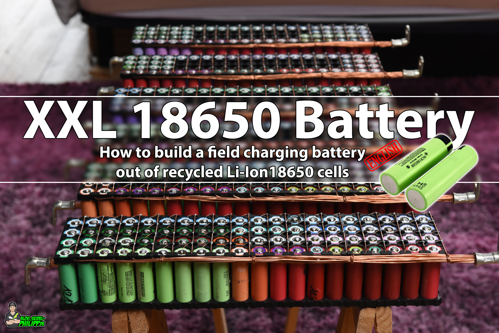
How to build a field charging battery out of recycled 18650 cells

![]()
Inhaltsverzeichnis
I’ve built a huge field battery, which will be charged via photovoltaic. For the battery type, I chose 18650 lithium-ion cells.
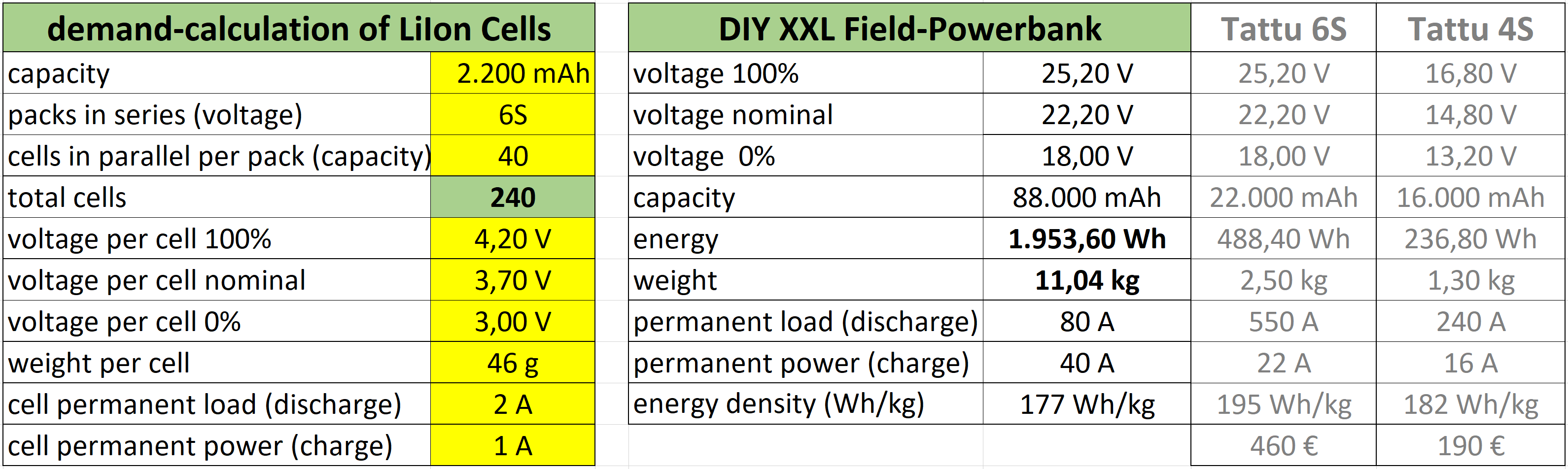
My goal is to build a battery that can store around 2KWh. I have decided to build a 6S40P battery with 22.2V.
Why 18650 cells
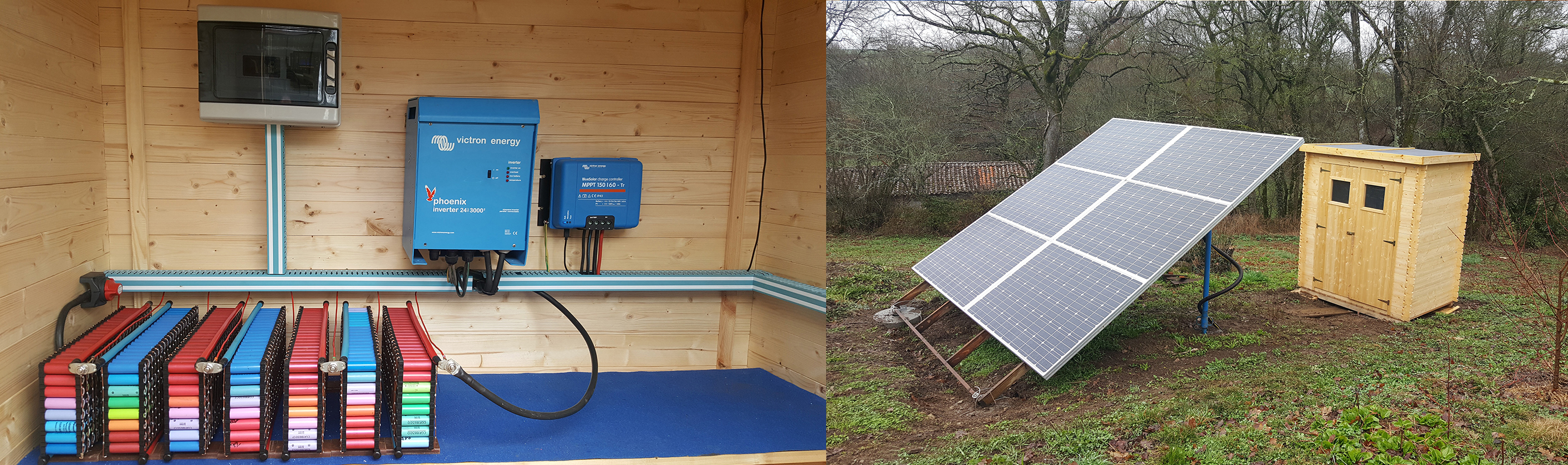
The Tesla Powerwall inspired me to use the 18650 Li-Ion cells. These cells have a very high energy density, no memory effect and you can leave the battery fully charged for a long time without it being damaged.
A small worldwide community builds their own powerwalls exactly this way and charges them via photovoltaic.
Where to get the 18650 cells


Another point why I chose 18650 cells is that you can find them in just about any battery. They are installed in power banks, e-bike batteries, laptop batteries or cordless screwdrivers. Unfortunately, old or defective rechargeable batteries are not recycled today and go into trash. However, if you open these batteries, you will find heaps of 18650er lithium ion cells. Most of the time, only a few cells of the battery are really damaged, and the rest can be tested for further use. In some cases only the PCB (BMS) is damaged and all cells are still working.
According to my calculator, for a 2KWh battery, I need about 240 good cells with an average capacity of 2200mAh.
Test method for used cells
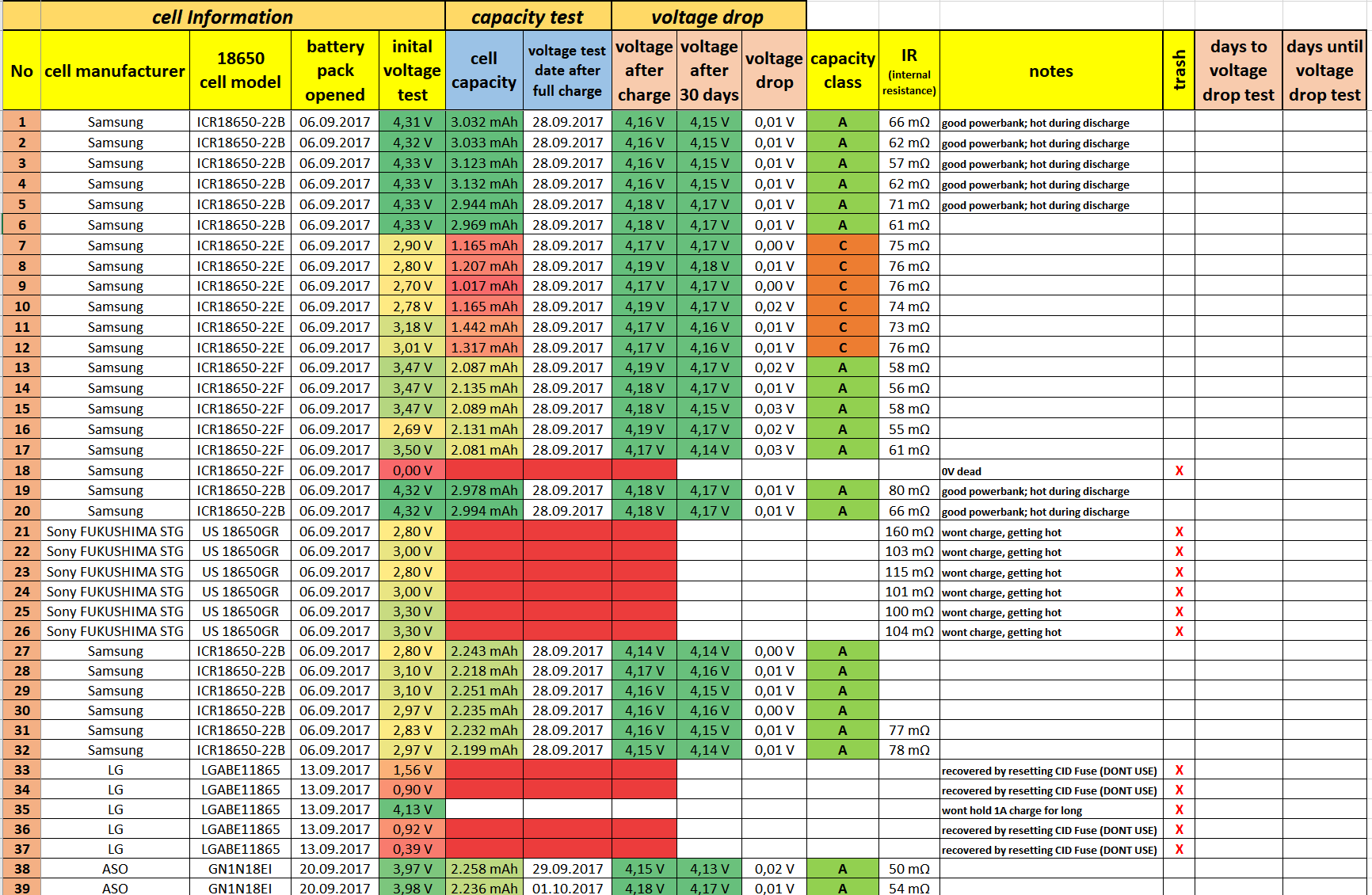
To test the batteries, I have created a spreadsheet in which I collect the most important data. The table calculates all values for me and makes it much easier for me to work with so many 18650 cells. It calculates voltage differences, divides the cells into different classes and much more. Here you will find the latest version of about 525 cells.
spreadsheet Download:

Mit dem Laden des Videos akzeptieren Sie die Datenschutzerklärung von YouTube.
Mehr erfahren
The test procedure explained in a few steps:
- Open battery and expose cells (remove welded metal sheets, adhesive, and tape)
- Measure the voltage and enter it in the list. Each cell gets a unique ID (consecutive number). Depending on how high the voltage is, pre-selected ( see 0V cells)
0 V cells are trying to be brought back to life with a laboratory power supply. A low current (100mA) is used to „boost“ the cell. As soon as the cell has reached about 3 V, I charge it with 500mA full.- Dead cells (0V) are binned
if they can not be revived. - Charge the cells (1A per cell) and sort out „Heater„. „Heater“ are cells that become extremely hot during charing. Cells that get warm should not be binned. As a rule of thumb, if you can not touch the cell and you feel your fingers burn, it’s a „Heater.“
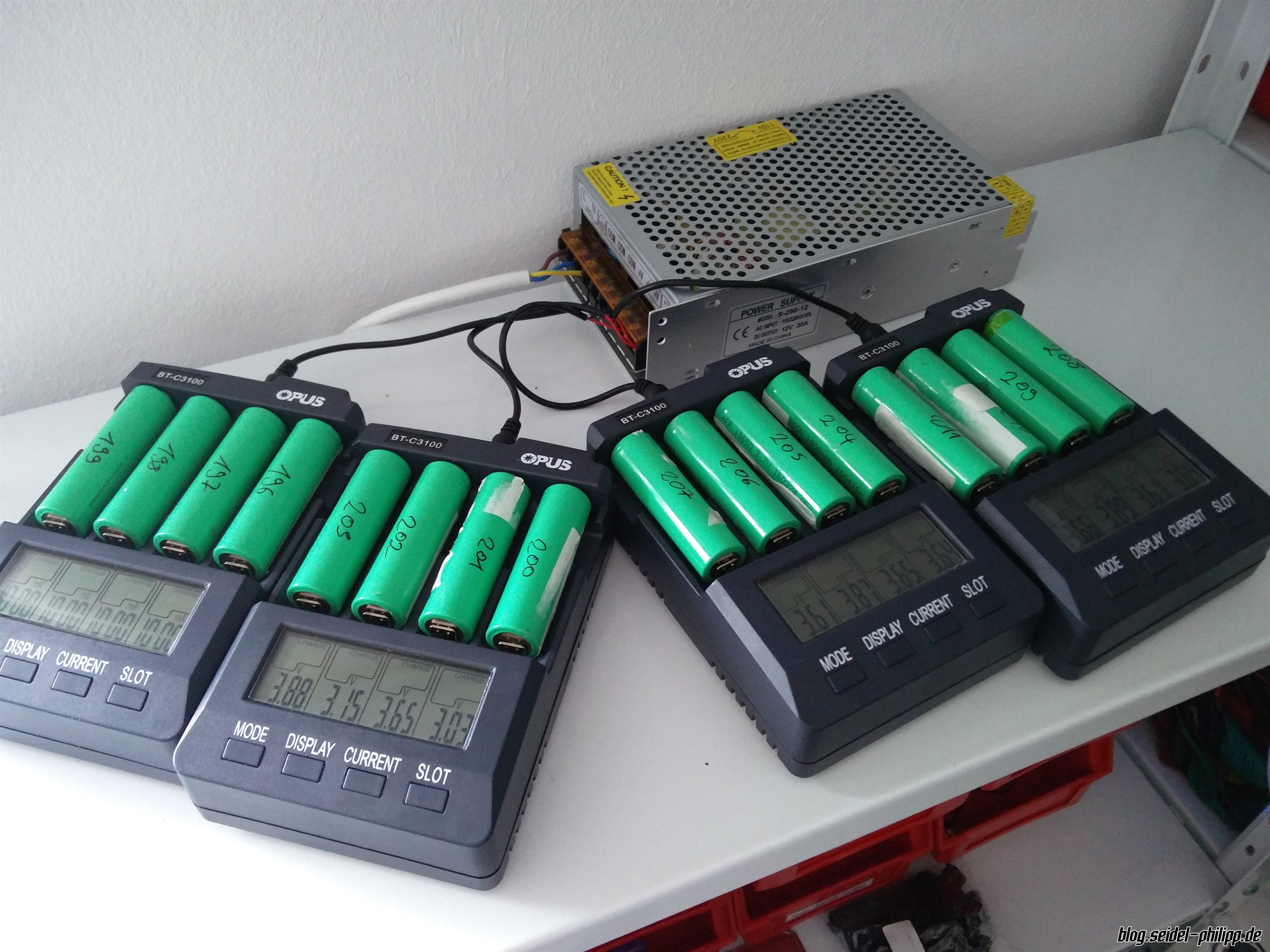
- Fully automatic capacity test with Opus BT-C3100 charger: Insert all full cells and select „Discharge Test„. The cells are now fully charged to 4.2 V if necessary and then discharged down to 2.8 V. The extracted energy is measured and displayed. After the discharge, the cells will be automatically charged to 4.2V again and are ready for the next test.
- Now, write down the voltage of the full cell. Since the Opus charger does not always charge cells exactly to 4.2V, I measure all the cells and write the voltage in my Excel spreadsheet.
- Measure voltage loss: After at least 30 days of storage at 4.2 V (cell is fully charged) I measure the voltage again. If the voltage drop is too high (> = 0.1 V), this means that the cell discharges itself. If you put such a cell in a pack of other cells, it would slowly discharge all cells connected in parallel. These cells, immediately go into the trash and must be sorted out urgently.
- Measure internal resistance. I measured the internal resistance with the SM8124A meter. But since I could not derive any added value from the obtained data, I stopped this measurement. All cells that fall through the previous tests usually have too high internal resistance and would also be detected without the meter.
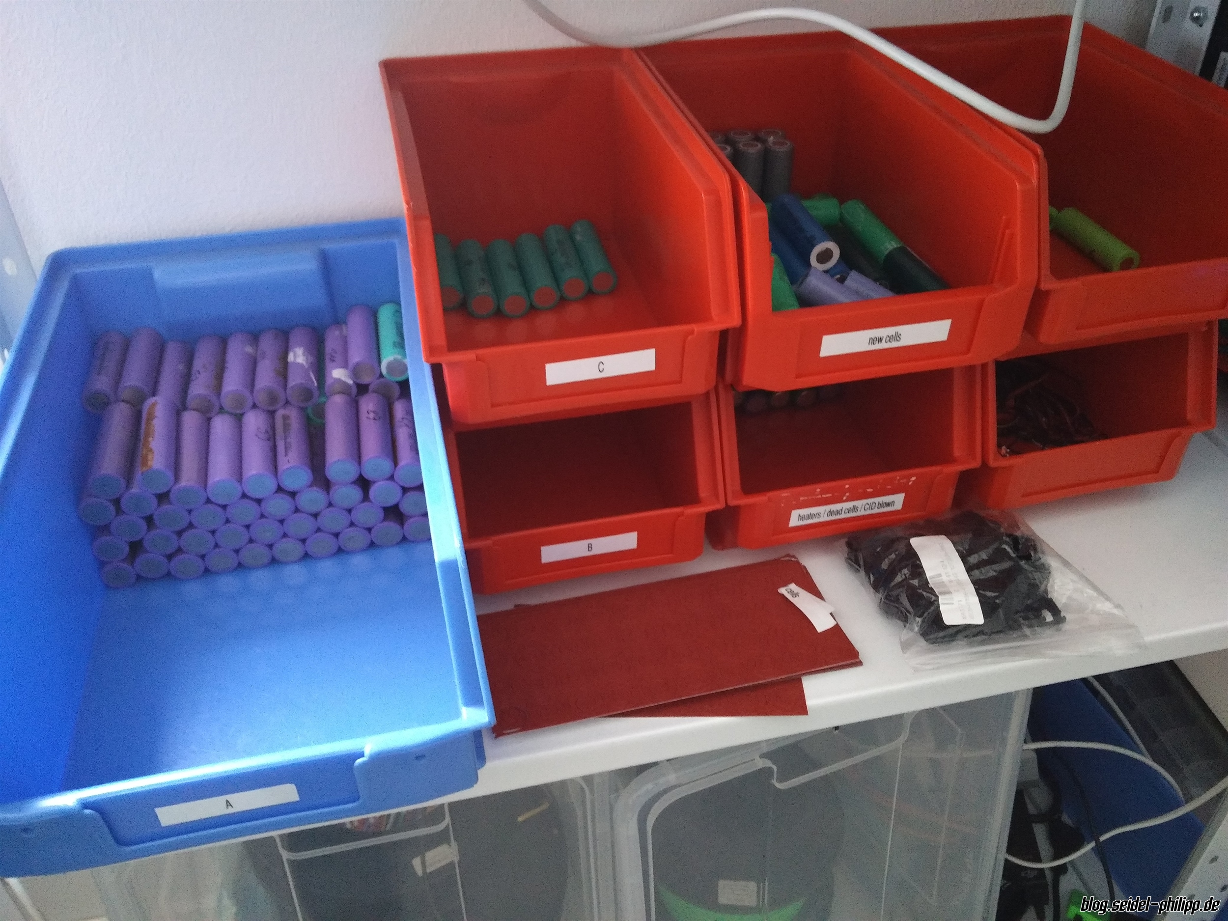
- Fully load 18650 cells and sort by capacity. I sort according to the following capacities:
Range class min max 0 mAh 499 mAh E 500 mAh 999 mAh D 1.000 mAh 1.499 mAh C 1.500 mAh 1.999 mAh B 2.000 mAh 3.500 mAh A
Statistics of tested batteries
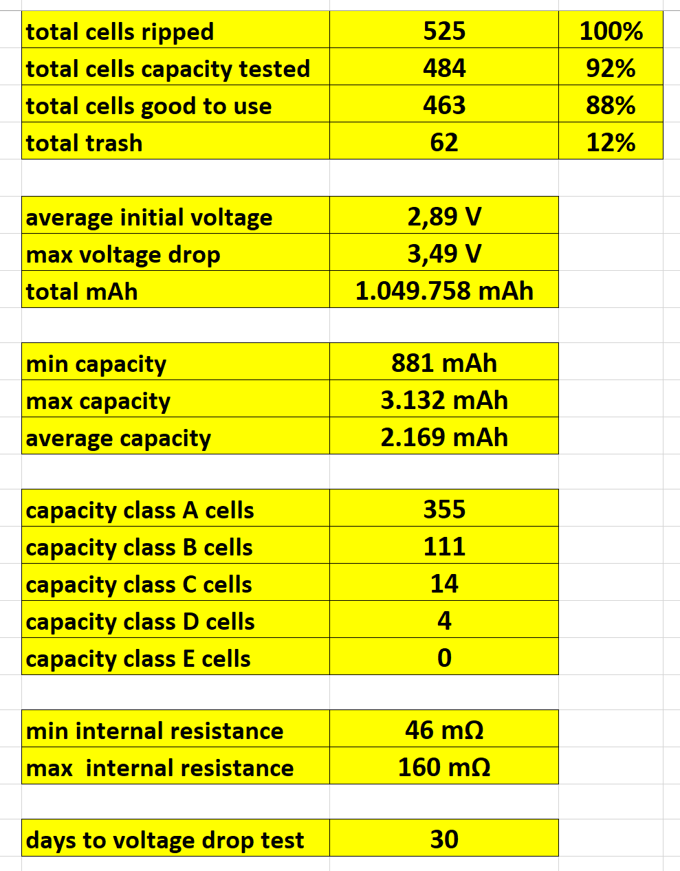
Currently I tested about 484 cells. Of 484 18650 cells there are about 12% reject (62 pieces).
capacity check
With the Opus BT-C3100, I test each cell for its capacity.
Voltage drop test
After the capacity check, I leave my cells fully charged about 30 days or more. Before the voltage drop test starts, I write down the voltage of each cell so that after 30 days I can tell exactly how much voltage the cell has lost.
If the cell is a „drainer“ (discharges itself), the cells must be binned and cant be used for the project.
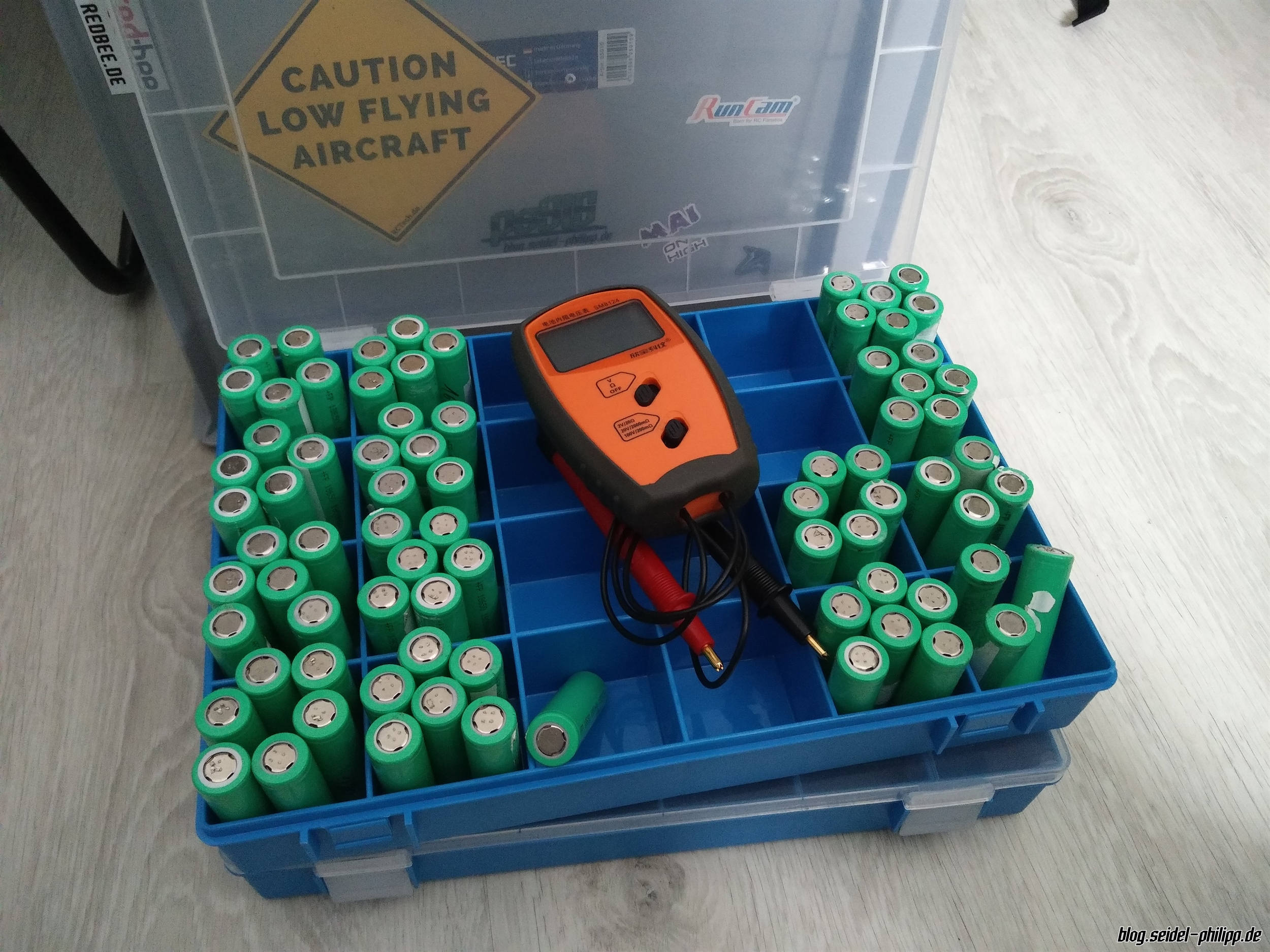
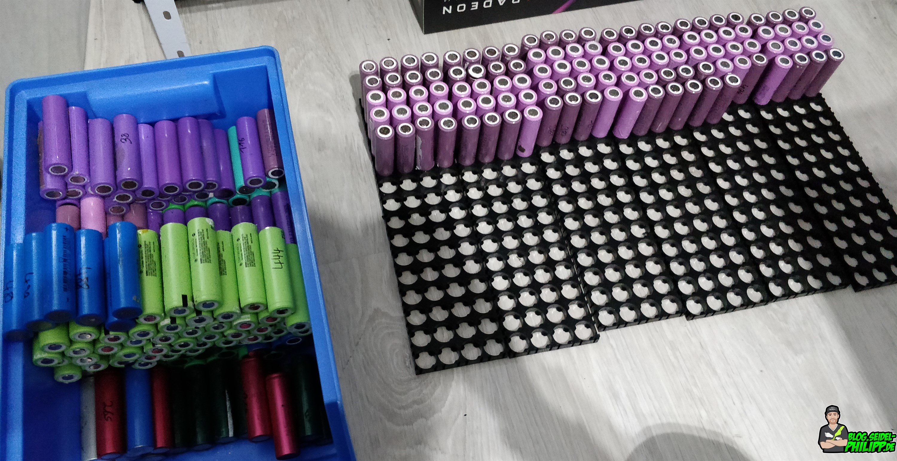
Sorting 18650 cells
After the voltage drop test, I sort the cells according to their capacity.
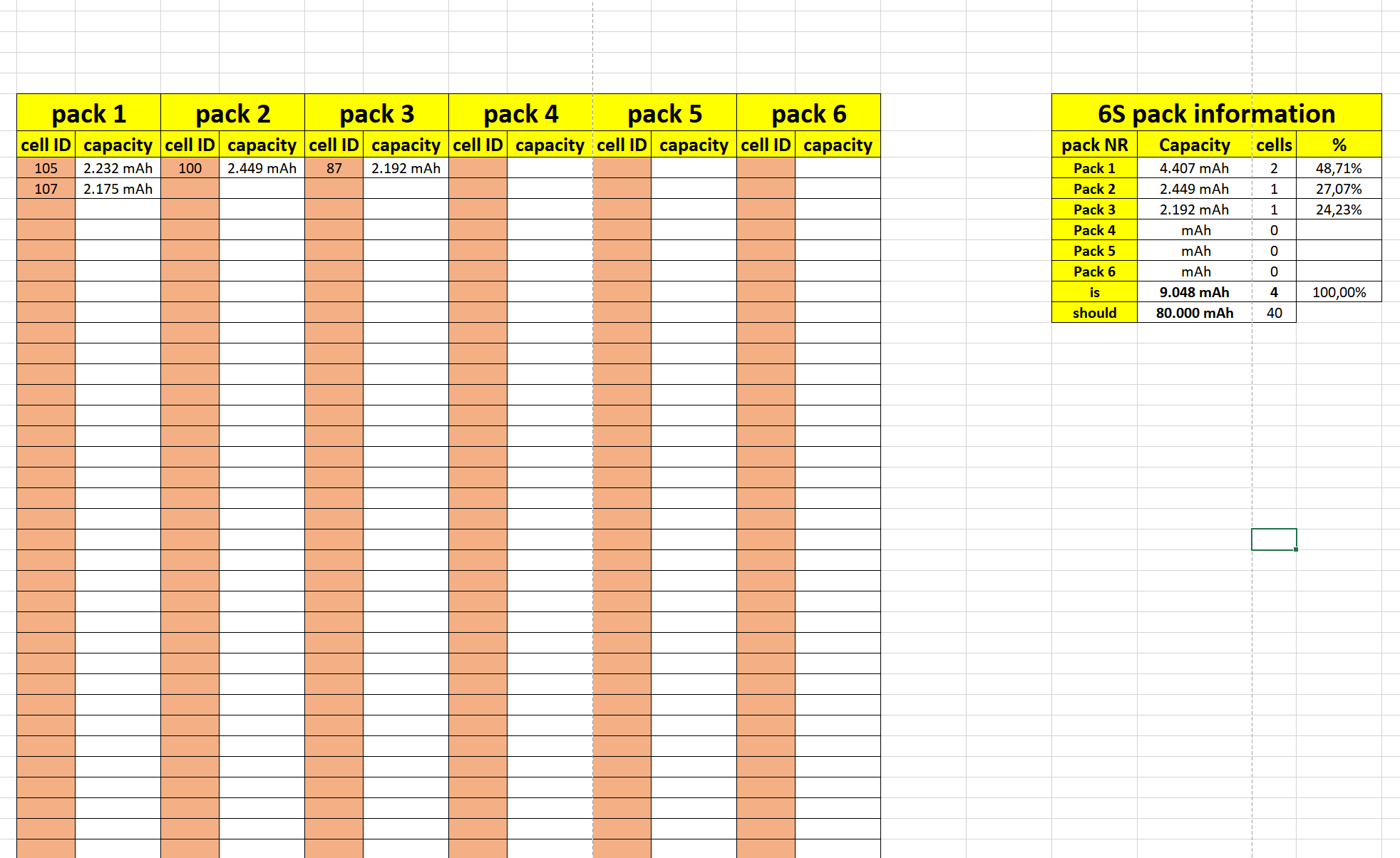
Pack Builder
I also „programmed“ a Pack Builder. All you have to do is enter the ID of the cell in the column of the relevant pack and calculate the capacity of the pack at the end. Why a Pack Builder: All 6 packs should have the same capacity as possible. This tool makes it easier to get the exact same capacity on every pack. Whether I will work later with this tool, I do not know exactly yet.
Update: I did not work with the tool due to time constraints and instead only installed category A cells. The cells I have divided in color (manufacturer/type) on all 6 packs to get as equal as possible capacity.
I will soon test each 1S pack and see how high the capacity really is.
Assembly
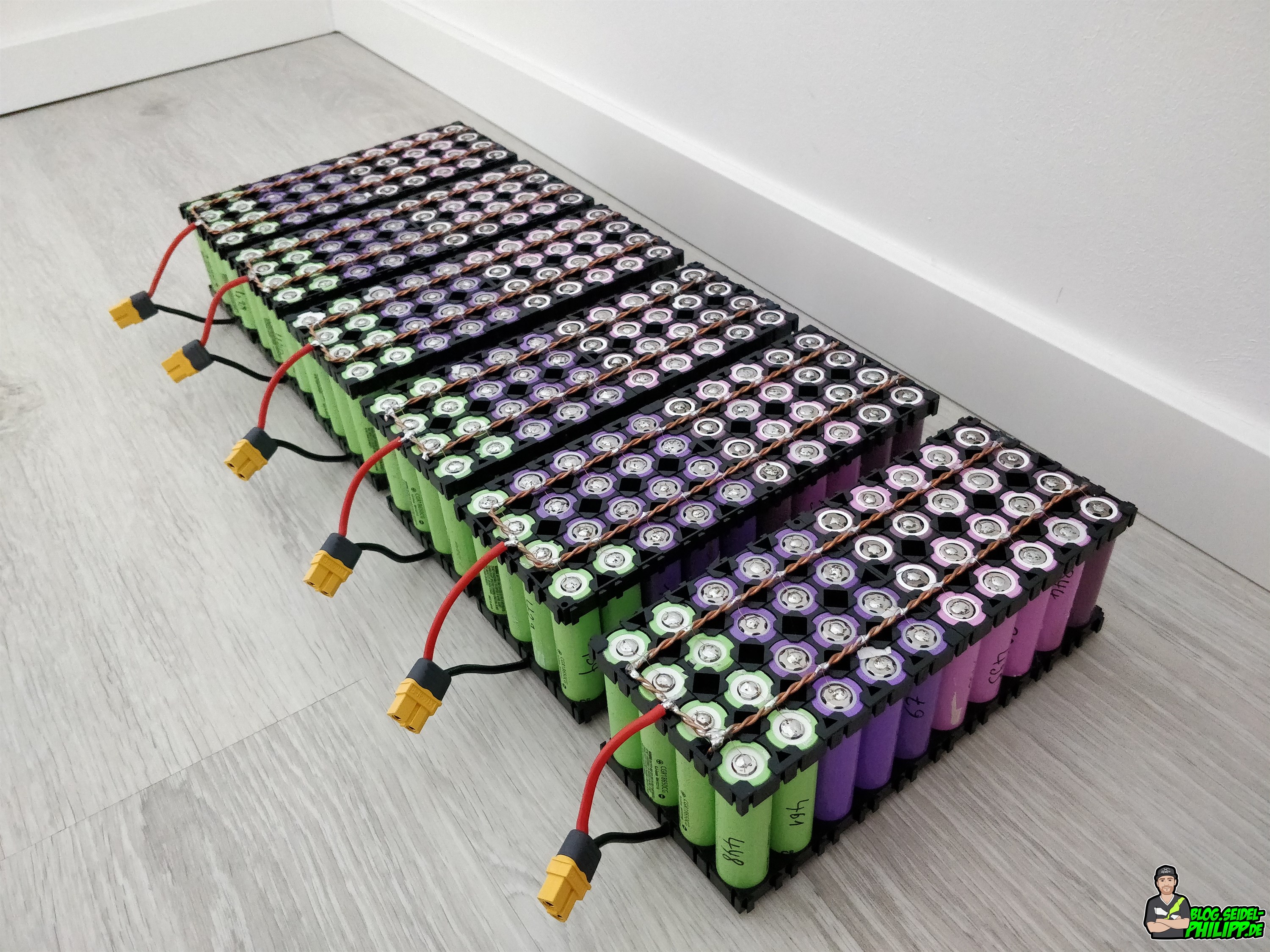
I have now tested over 500 cells and you could go on and on. I have now decided to build a large 6S battery from all „A cells„. I will connect 40 cells in parallel for each package. In the end it will be a 6S40P.
The battery:
- 240 recycled 18650 lithium-ion cells
- 6S40P (6 packets of 40 cells in series)
- estimated capacity / energy: 88,000mAh or 1,953.60Wh
- Voltage 100%: 25,20 V
- Nominal voltage: 22.20 V
- Voltage 0%: 18,00 V
- Discharge. 80-120 A
- Max. Charging current: 40 A
Material for assembly
- plastic cell holder 5×4
- Solder
- Solderring Station + Solderiron mit big solder tip
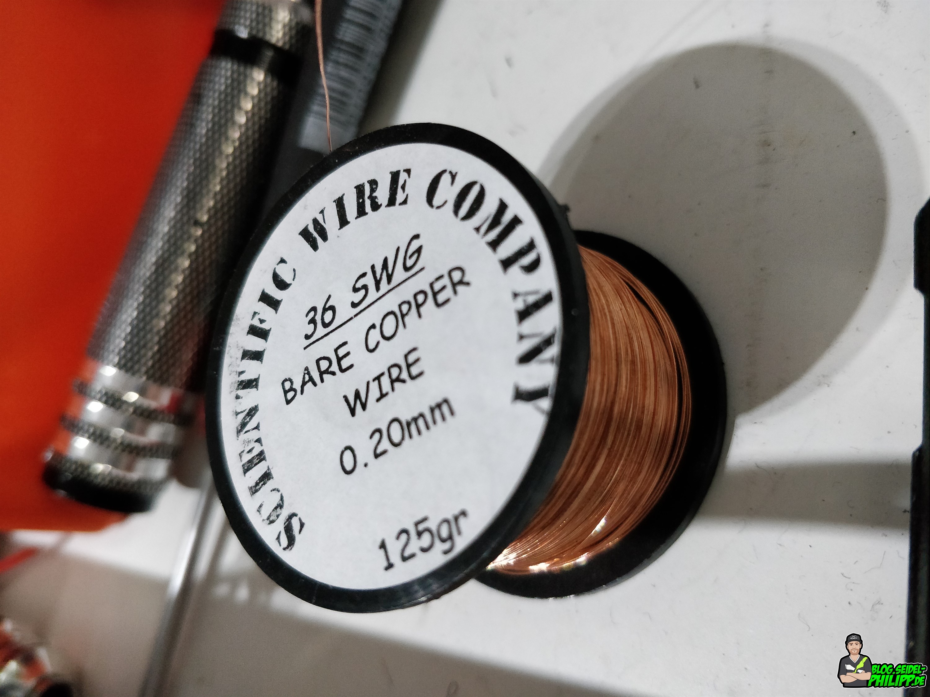
- 0,2mm bare Copperwire for „Fuse-Wire“
- XT60 Connector + Cable
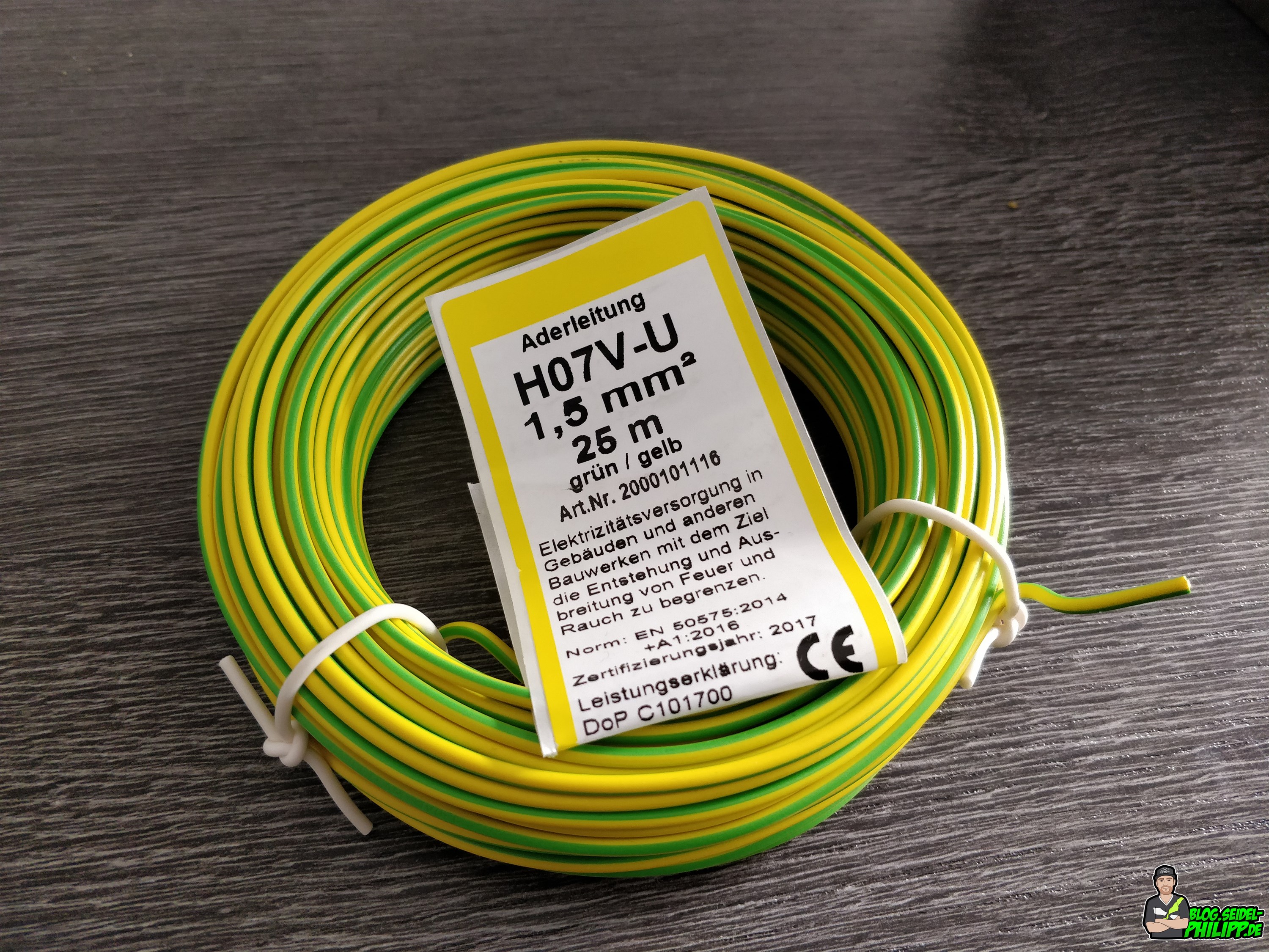
- Copper Wire 1,5mm²
- Cordless Screwdriver
- Dremel with sanding attachment
- Wirecutter & pliers
optional:
Divide cells
I divided the A-Cells by color on all 6 packs to get as equal as possible capacity. The probability that the same cell types have the same capacity is relatively high, which is why I sorted the cells by color.
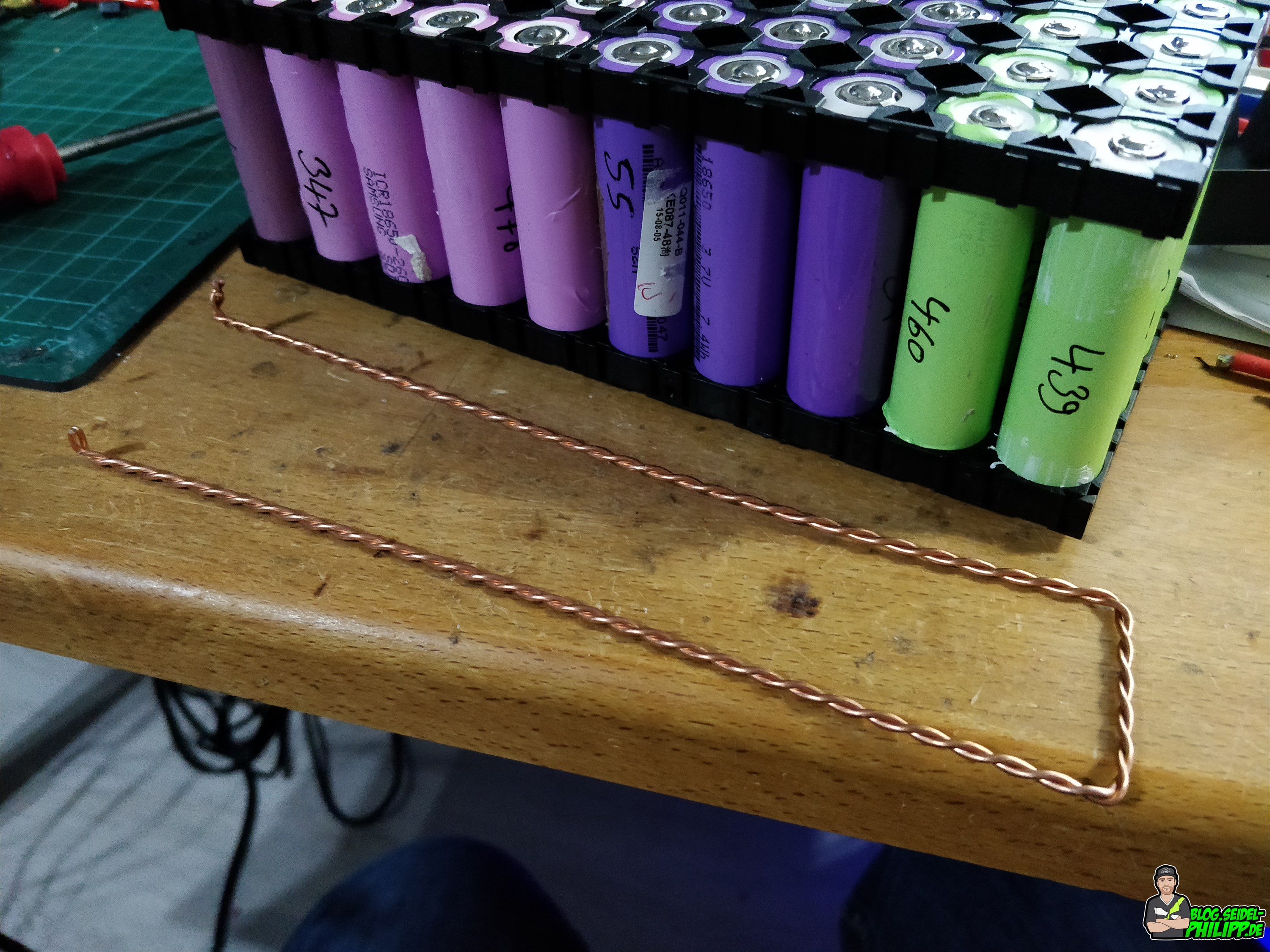
Produce copper busbar
I twisted the copper wire with a cordless screwdriver. After that, cut all the wires to length.
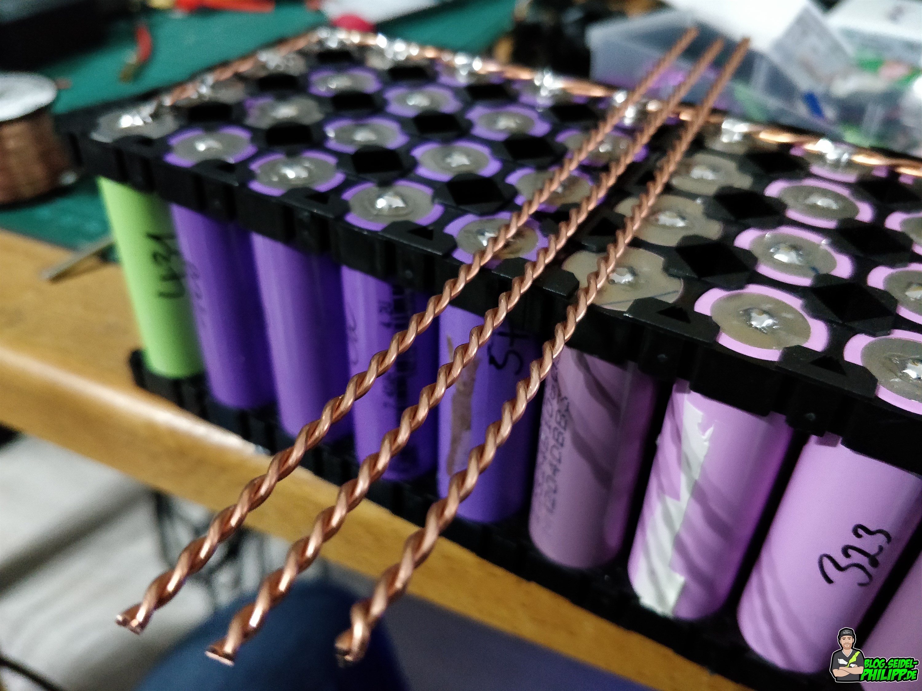
For the plus pole I bent the wire as follows.
Solder minus poles
Now I’ve connected all the negative cells first. I sanded the contacts slightly with the Dremel and a sanding attachment to get better solder joints.
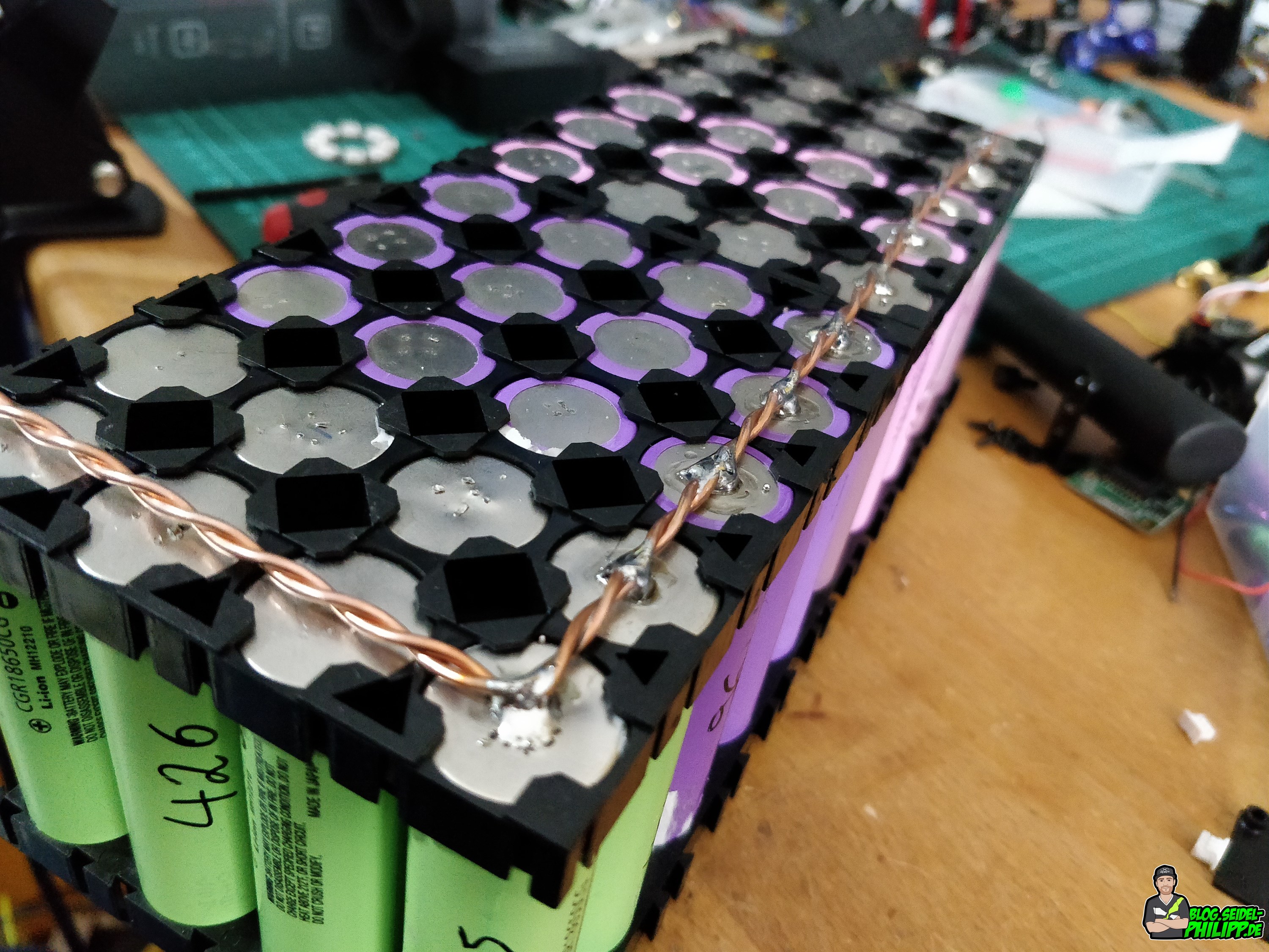
This is what a pack looks like with a soldered negative poles.
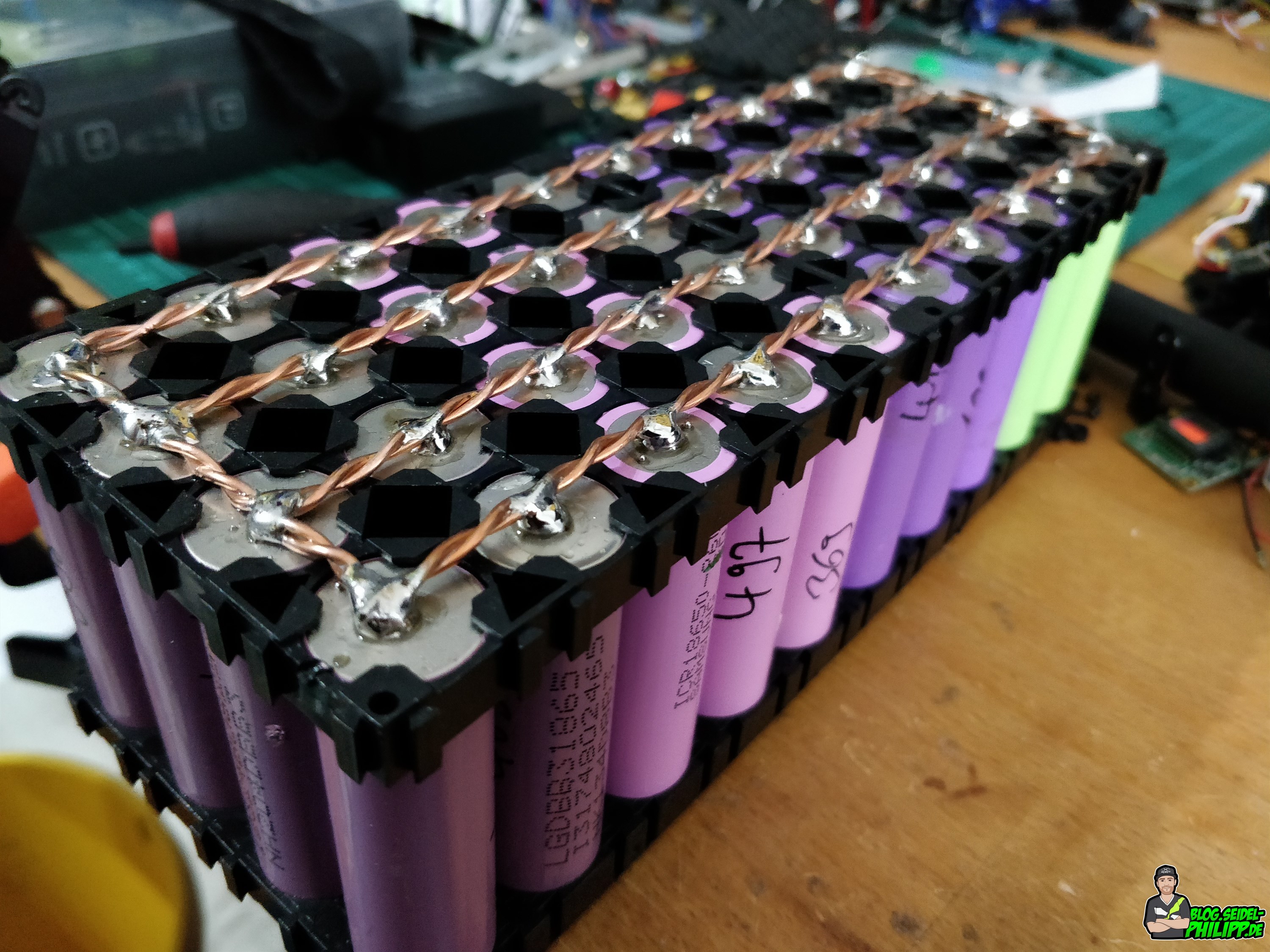
Solder the positive pole
On the „+ side“ of the battery pack, I have now fused each cell with a „FuseWire“. This is extremely important for safety reasons. If a cell has a short and „burns out“, the cell automatically disconnects from the rest of the pack.
Once all the 18650 cells are connected, they begin to balance themselves so each cell has the same voltage.
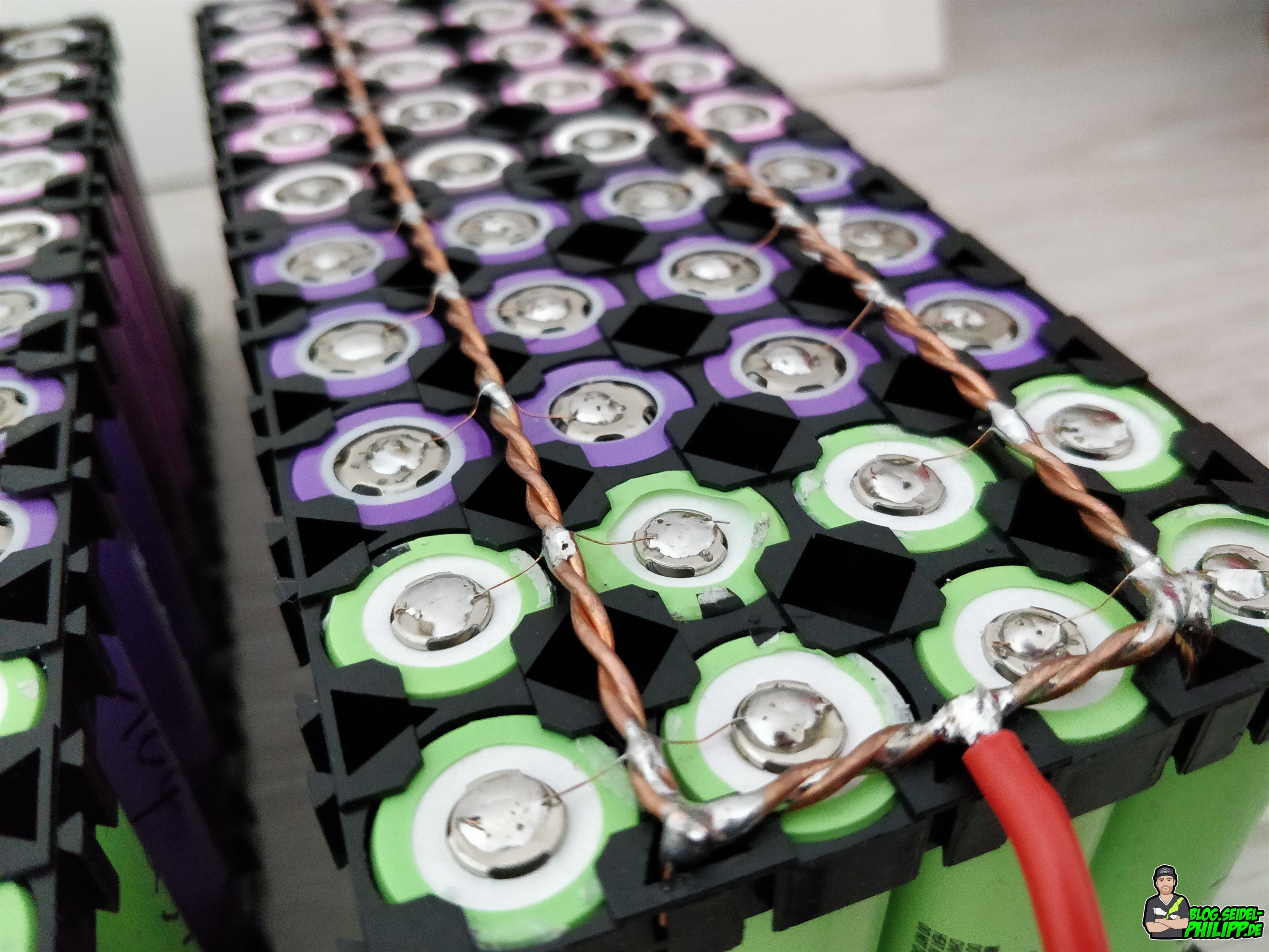
Solder XT60 cable
The last step is soldering an XT60 cable. Please pay attention to the correct polarity of the Xt60 connector. If you make a mistake and later put the packs together, the whole battery will explode and my burn down your house!
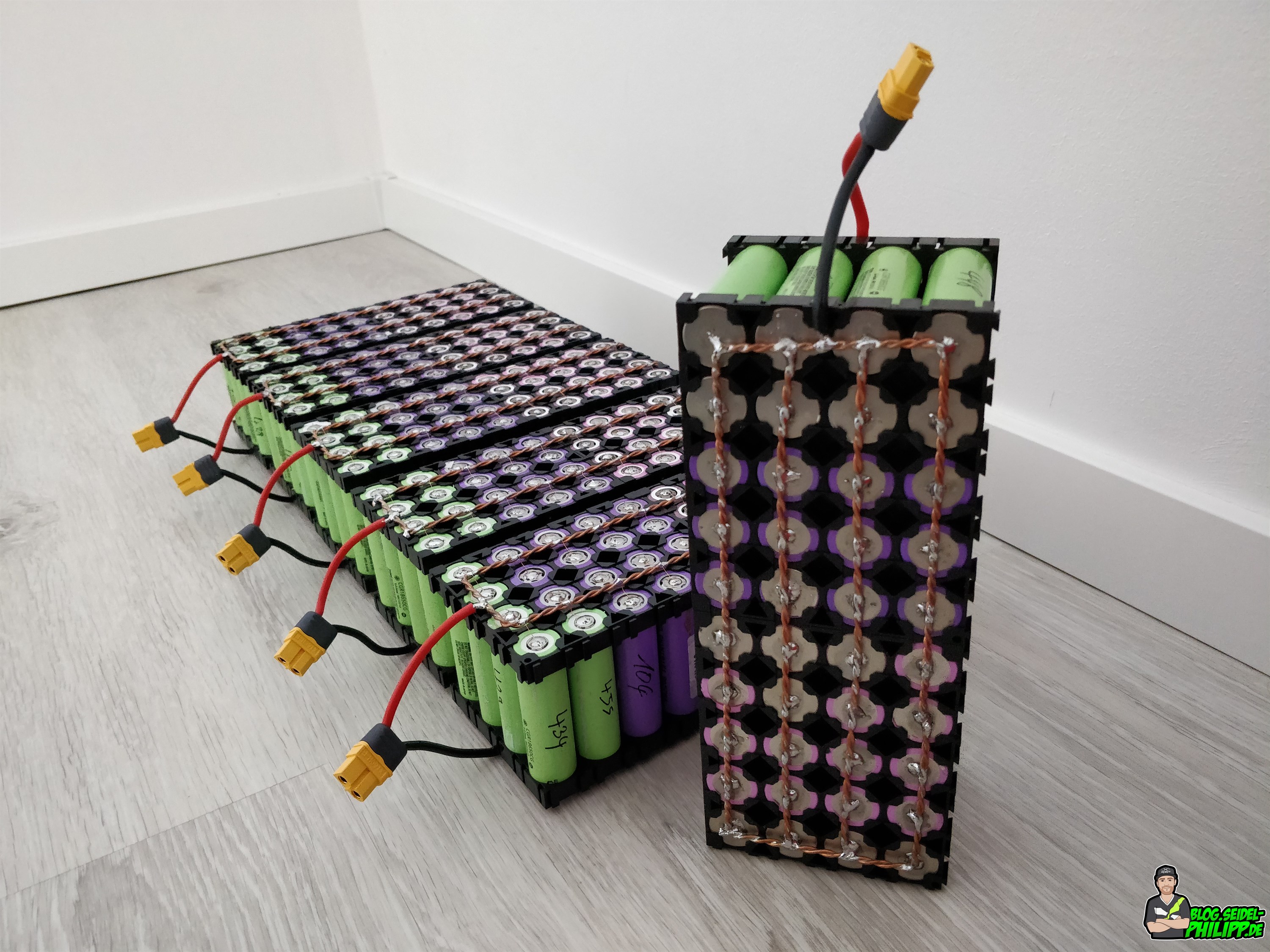
Here a photo of the back (negative pole)
connect to 6S
To be able to switch all 6 packs together to a 6S battery, you now need a special cable like this:
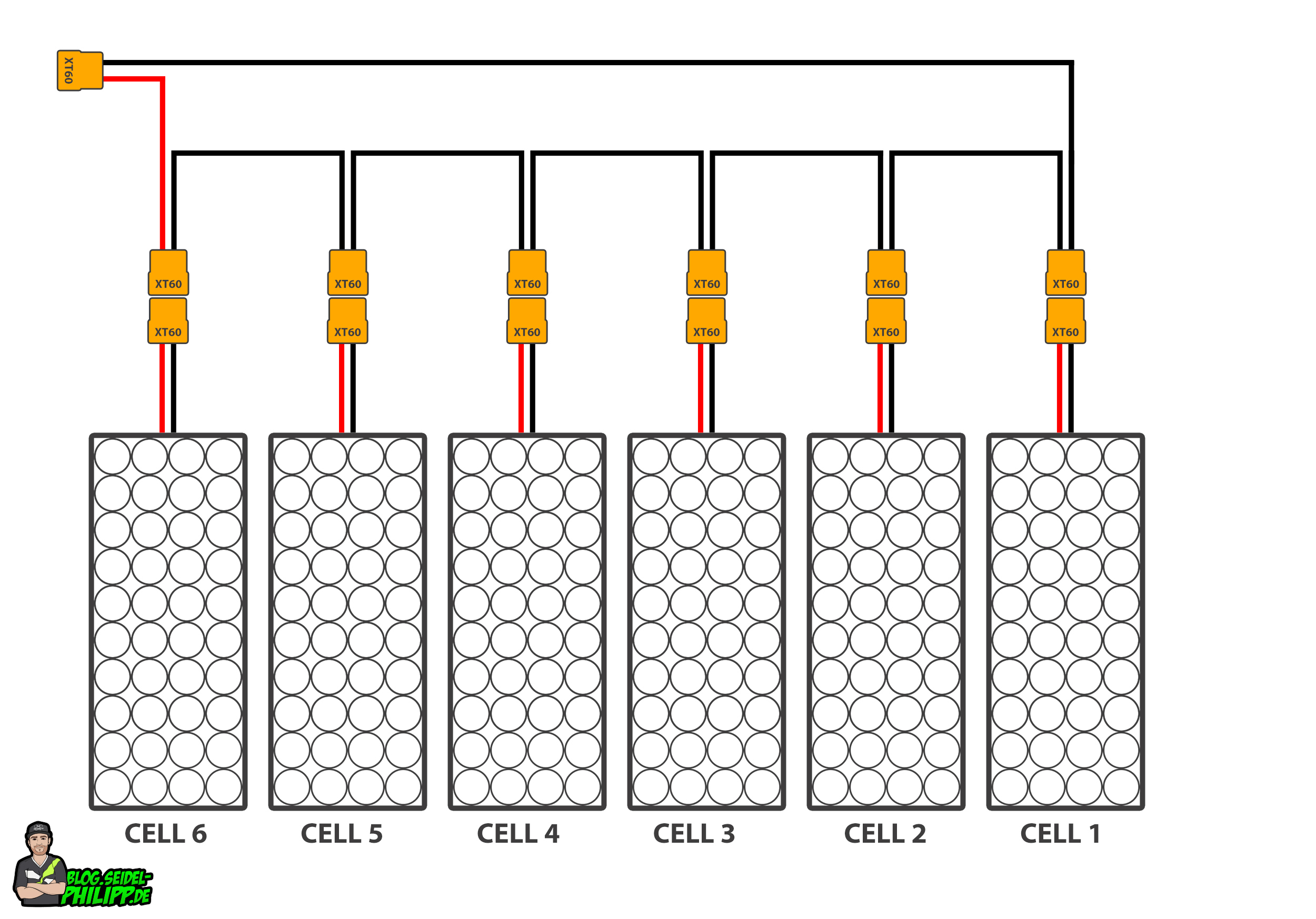
If a balancer is to be connected, the balancer connections must be wired as follows.
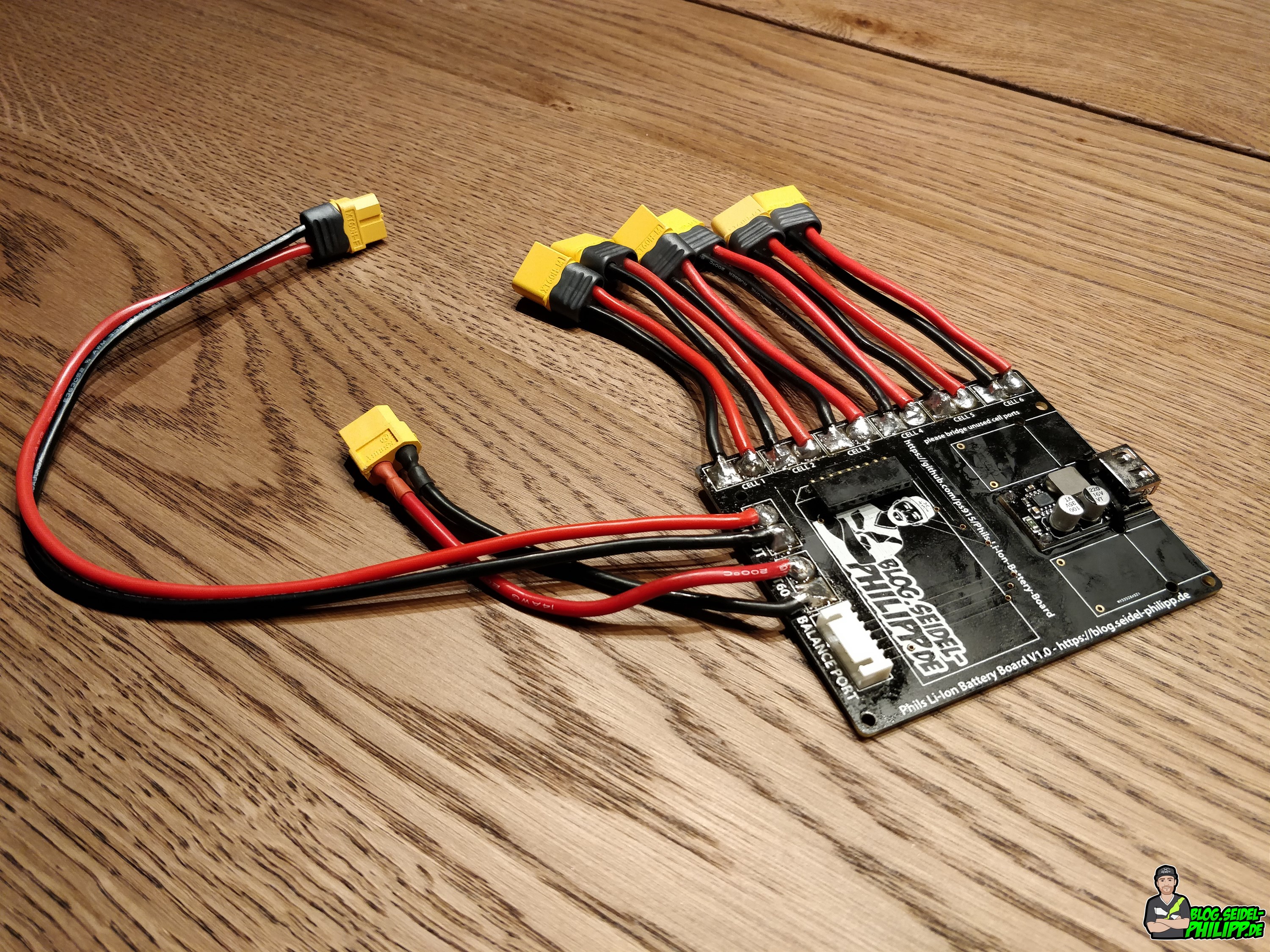
„Phils-Li-Ion-Battery-Board“
Mit dem Laden des Videos akzeptieren Sie die Datenschutzerklärung von YouTube.
Mehr erfahren
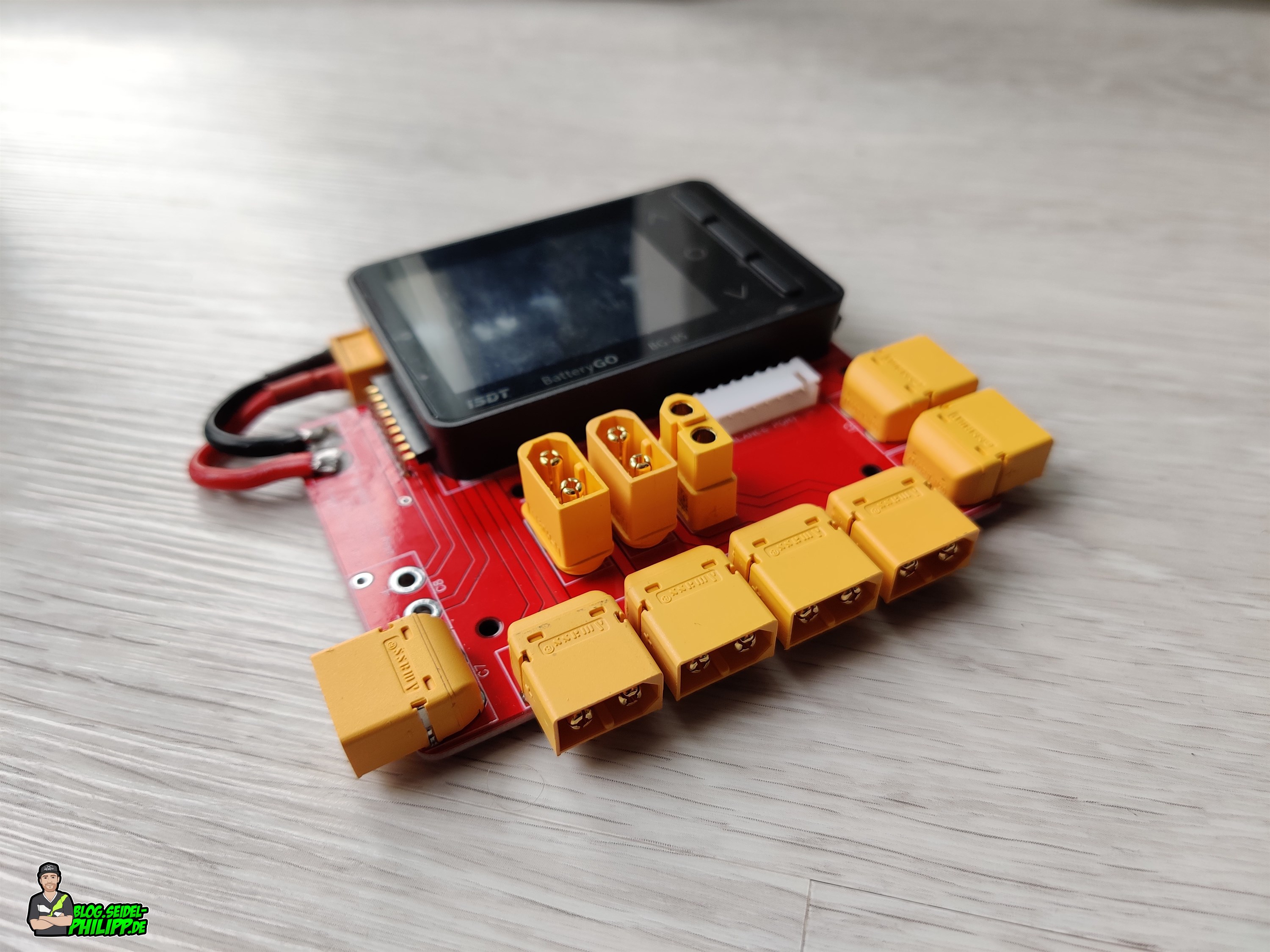
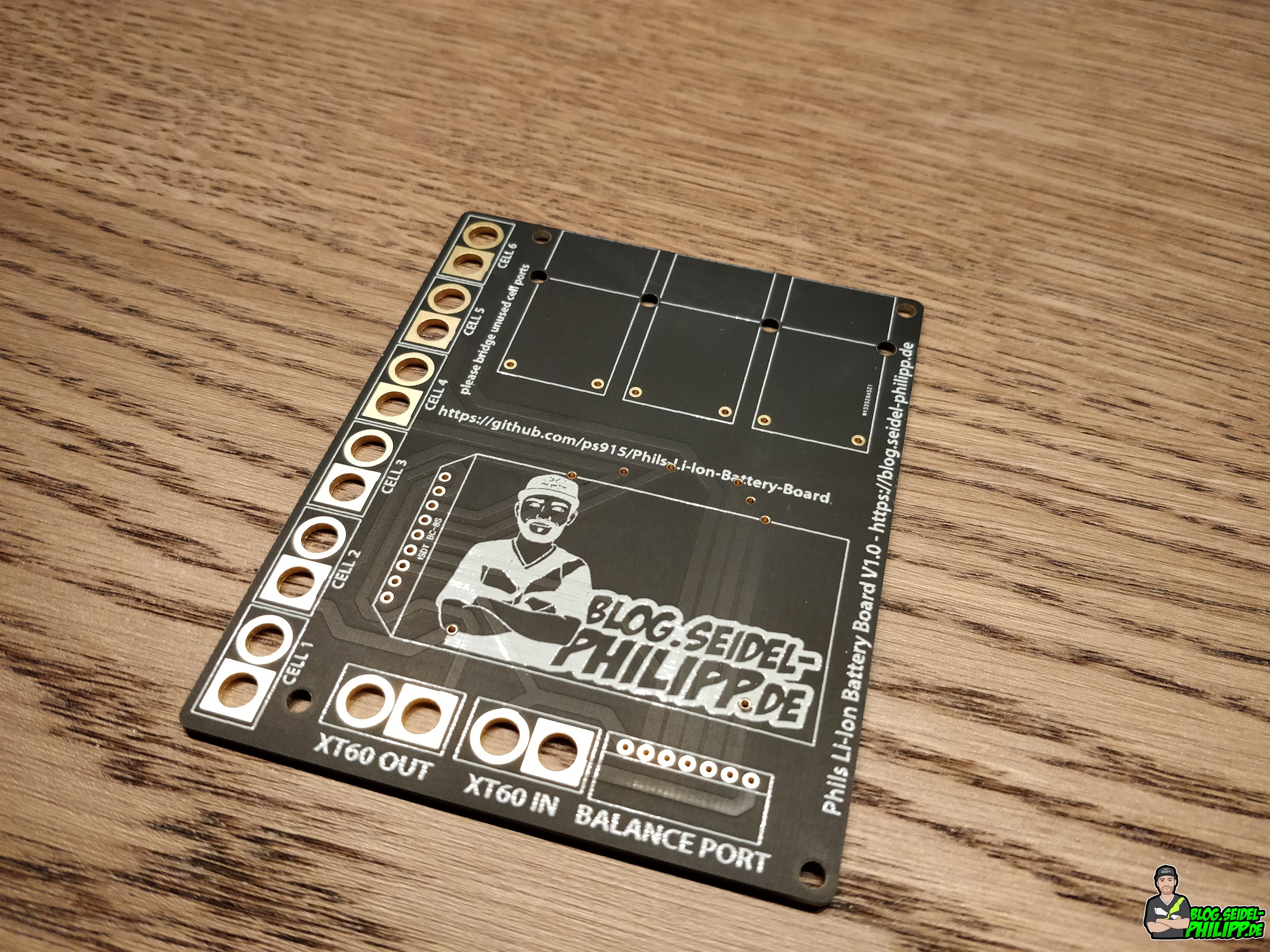
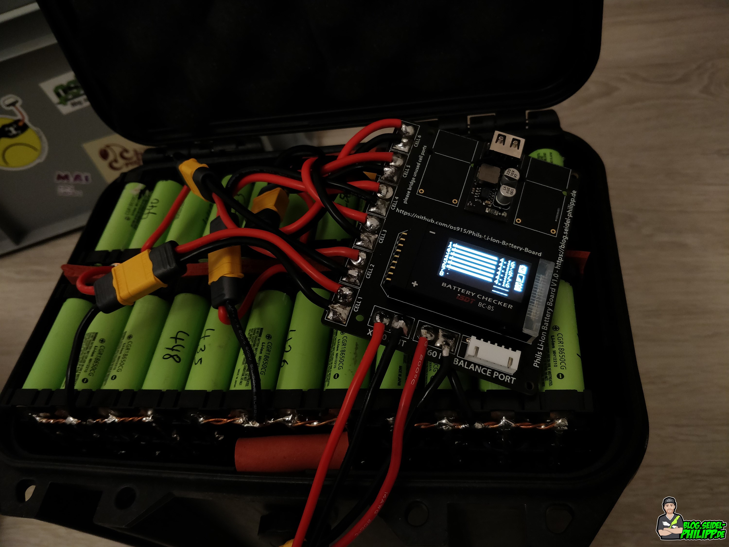
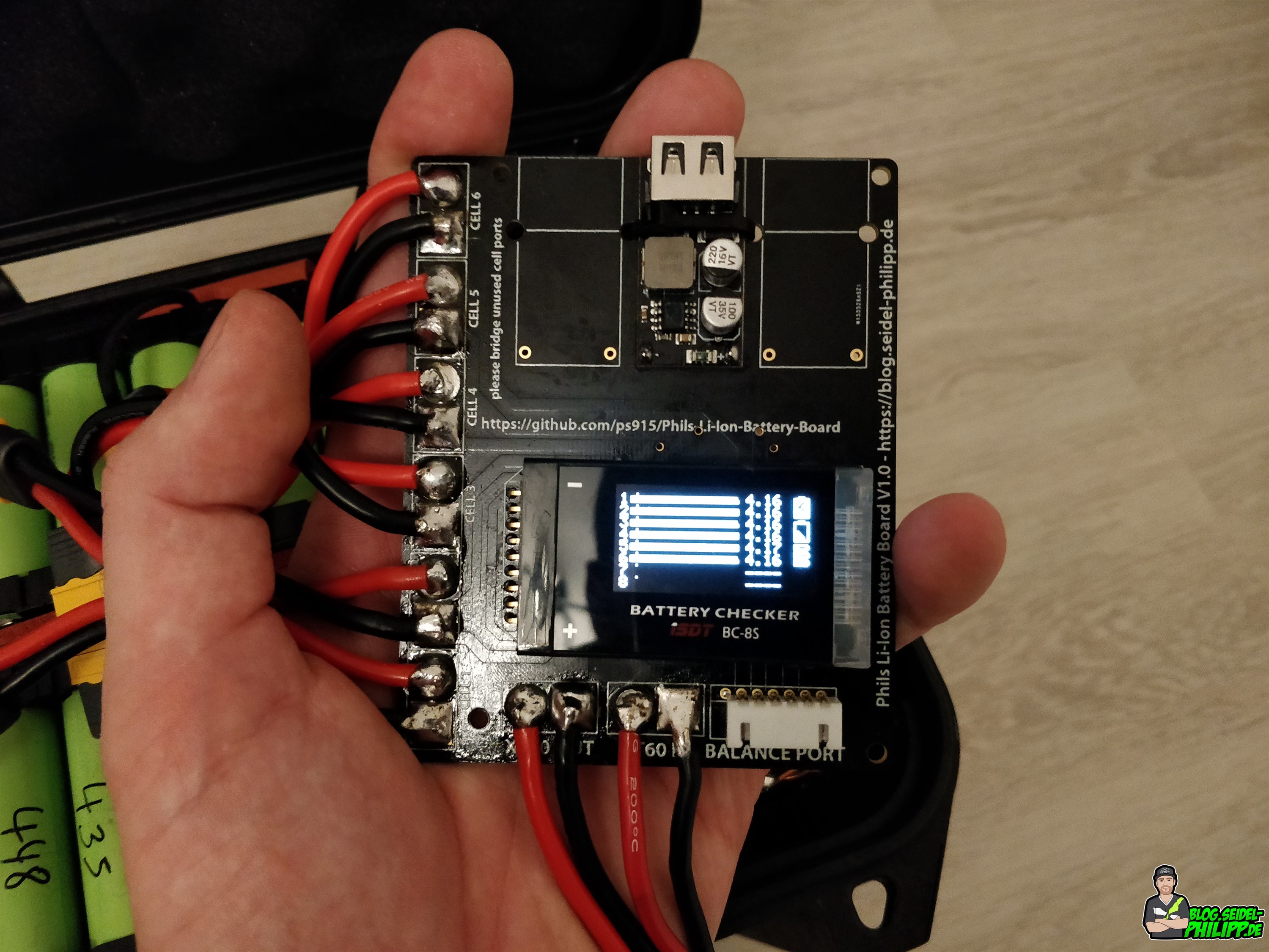
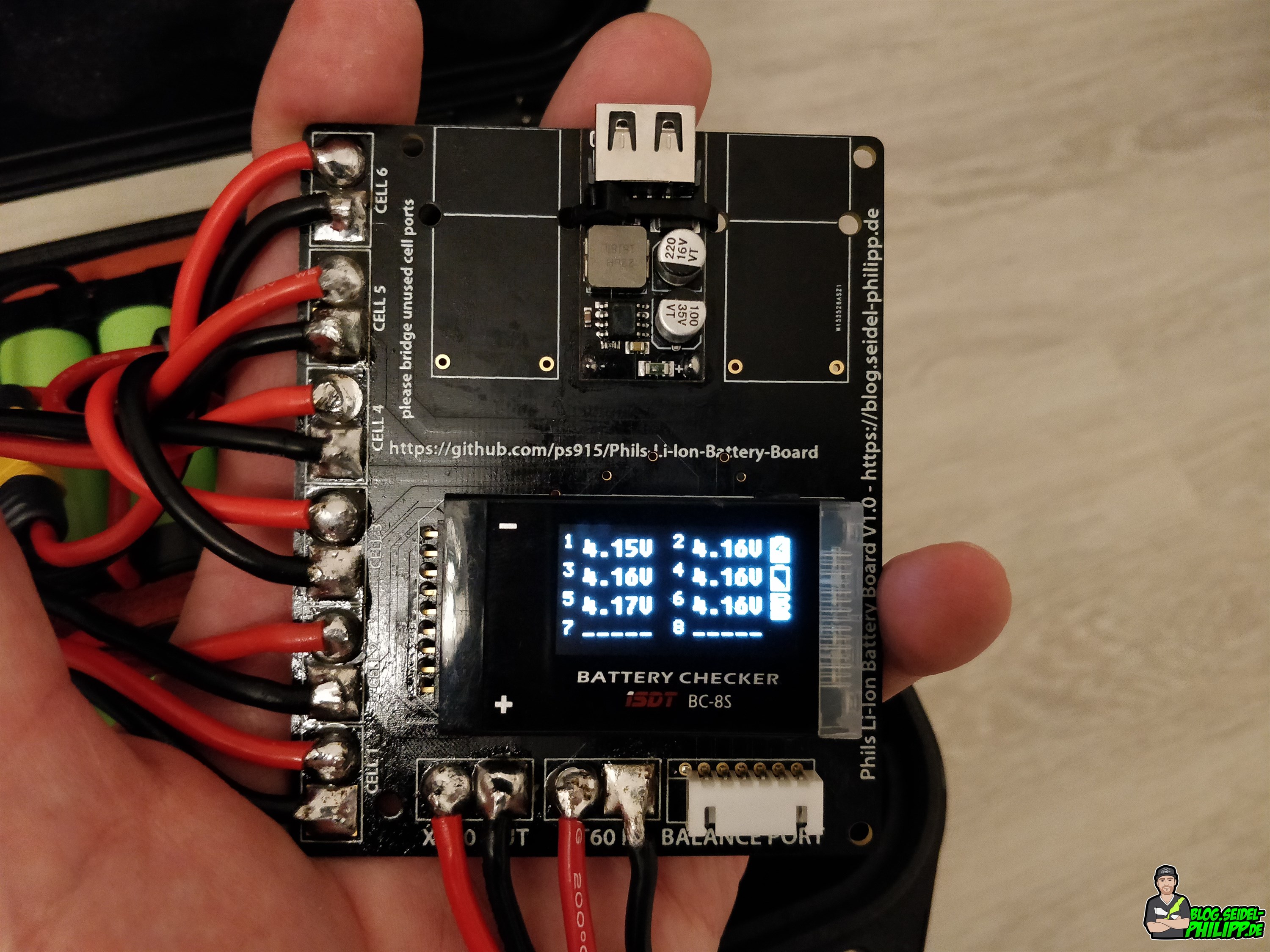
I designd my own PCB. My goal was not to solder any balancer cables to my batteries and to do the cell monitoring with an ISDT BC-8S (Amazon).
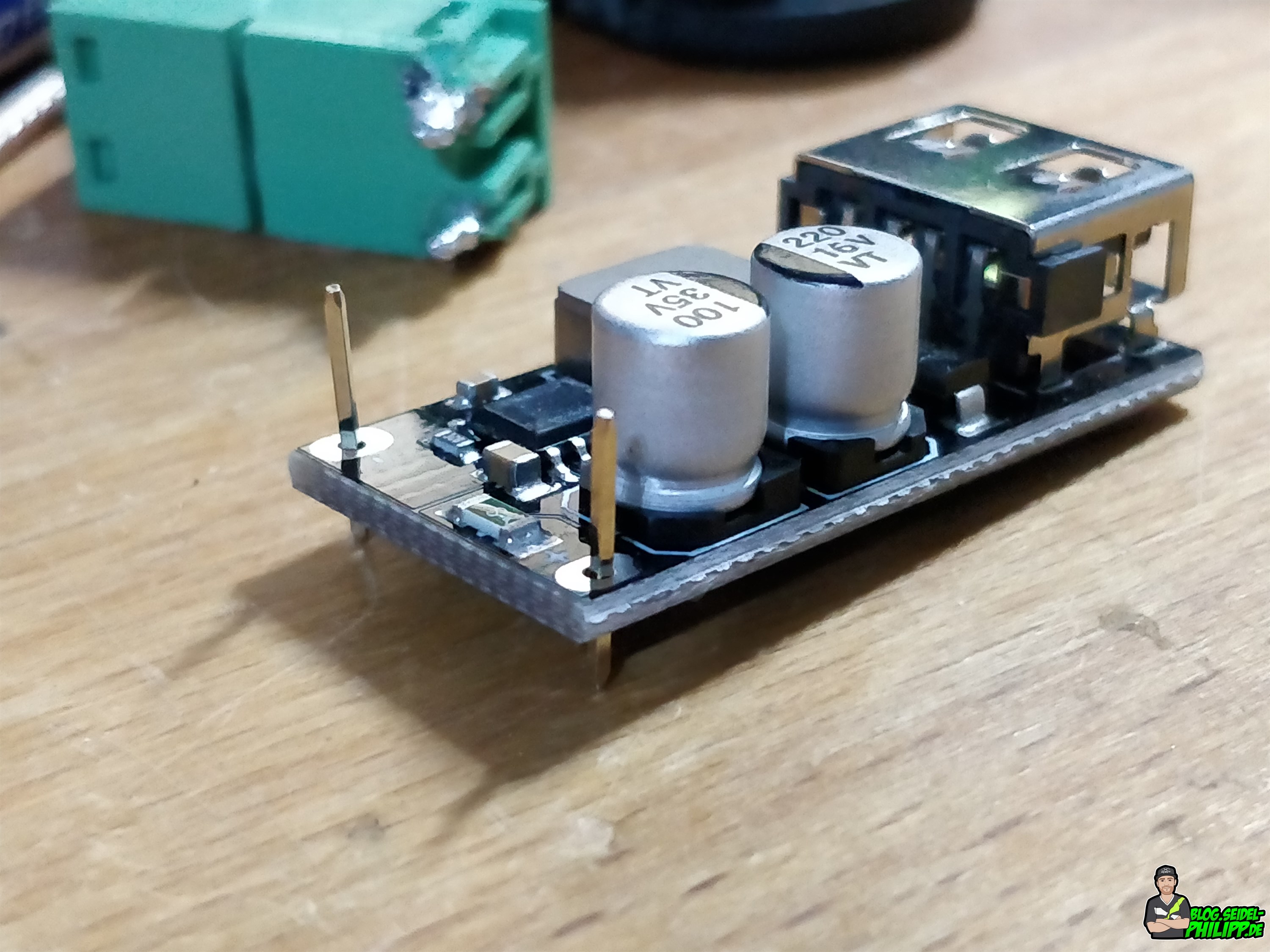
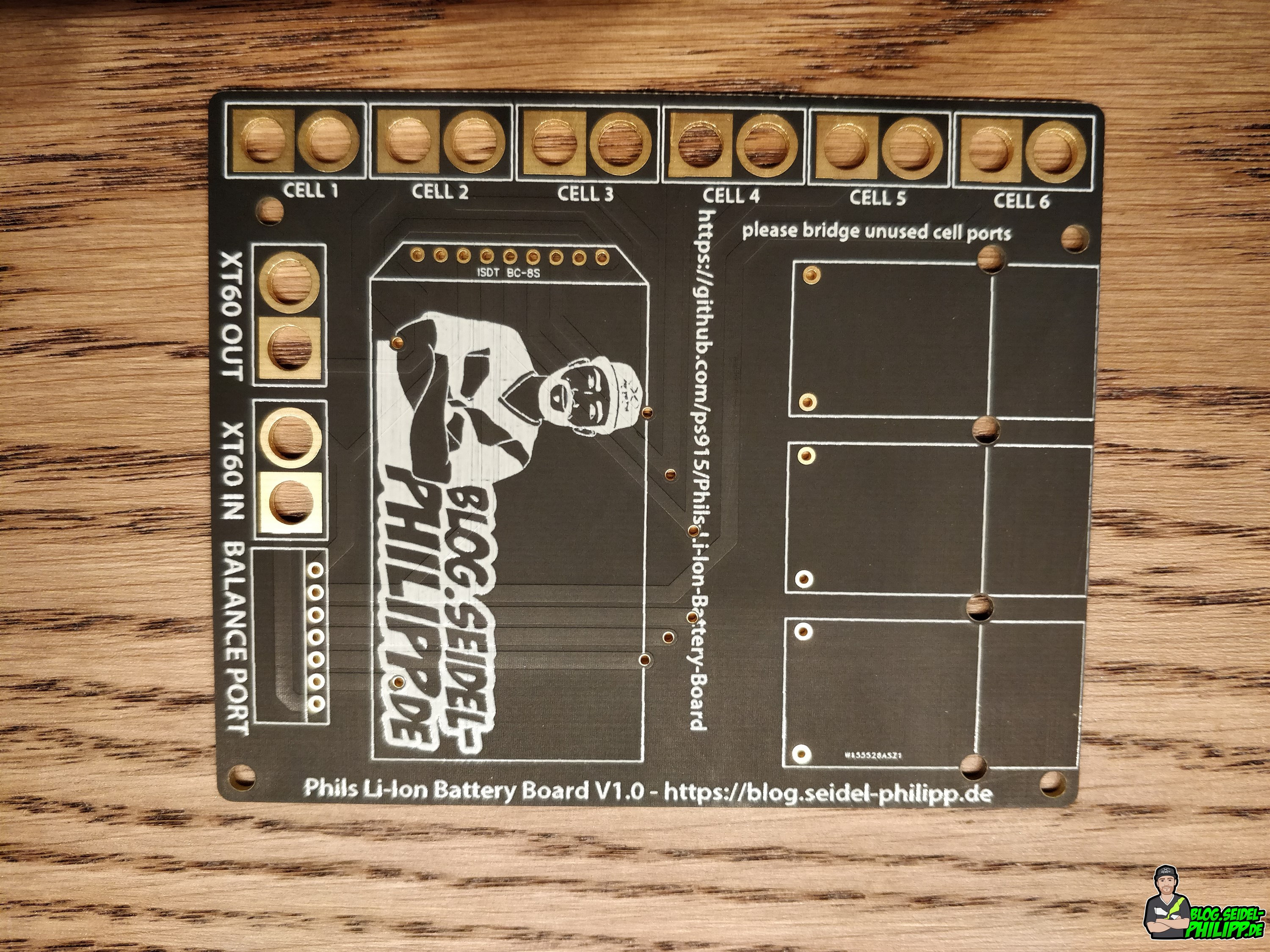
The PCB measures approx. 10x8cm and includes 6 cell inputs, an output, a charging port and a balancer connector. In addition, a BC-8S is installed for cell monitoring as well as places for up to 3x 5V USB outputs to charge other hardware.
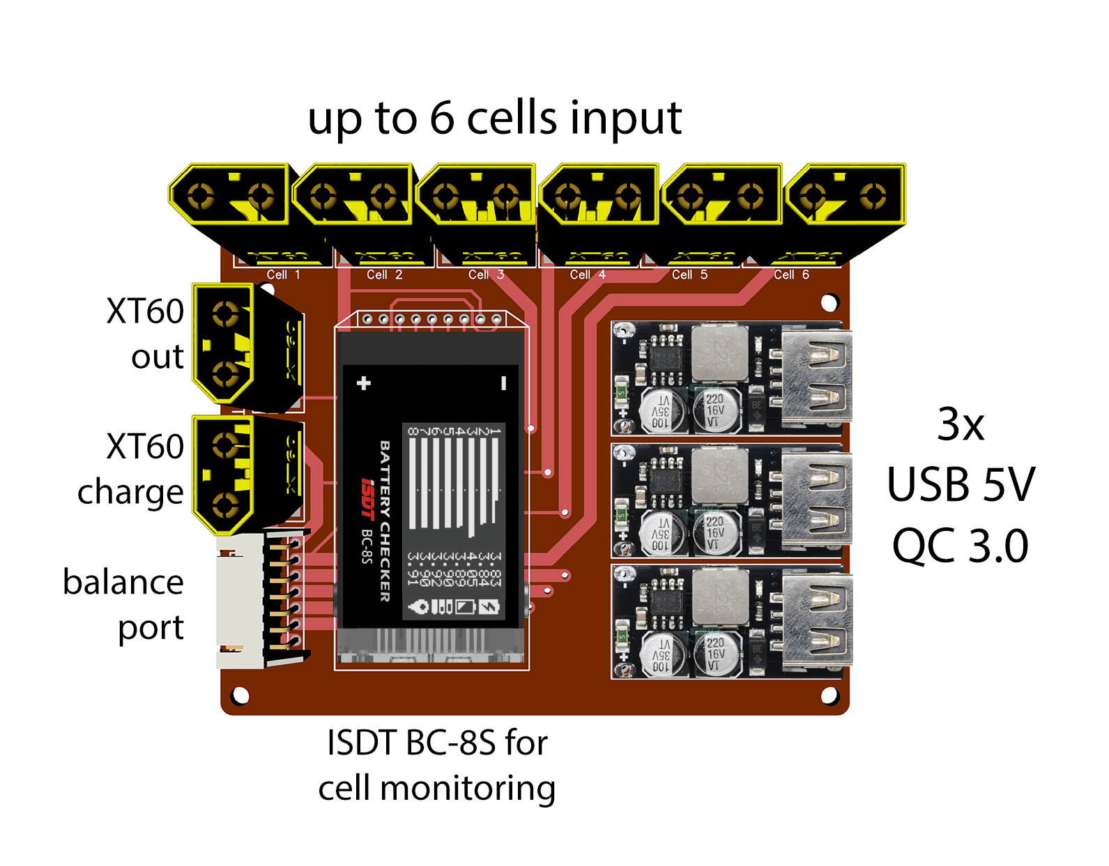
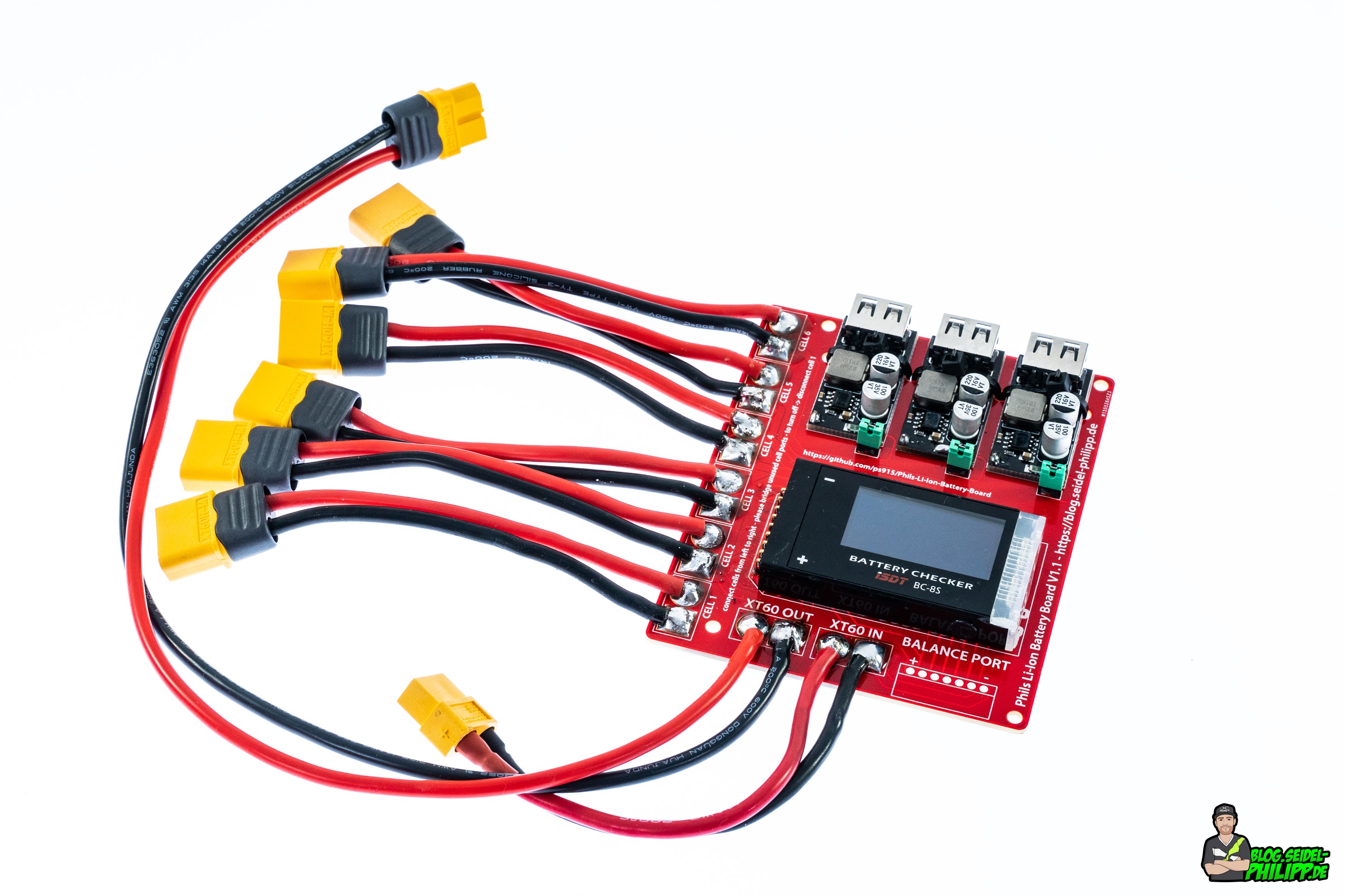
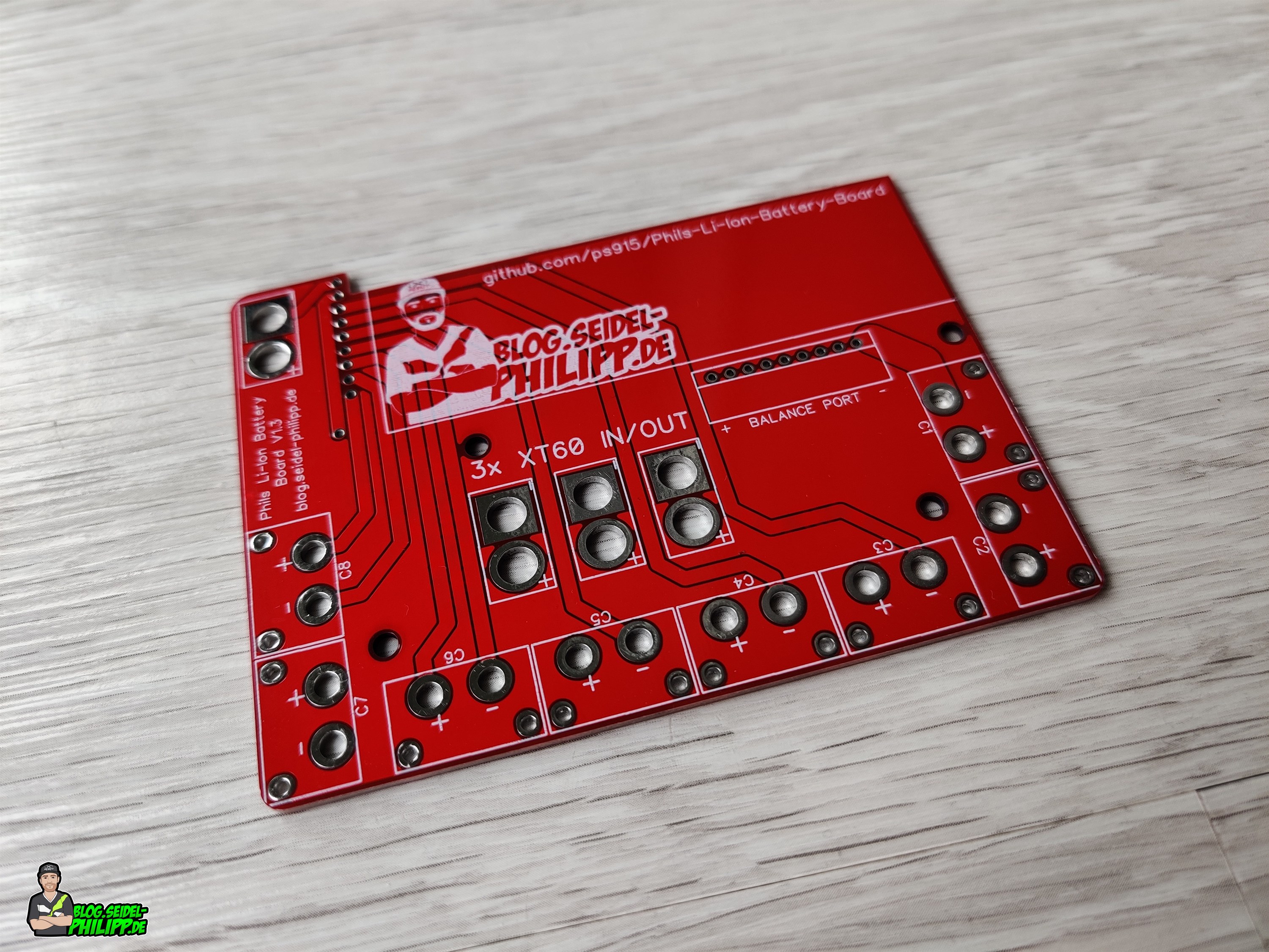
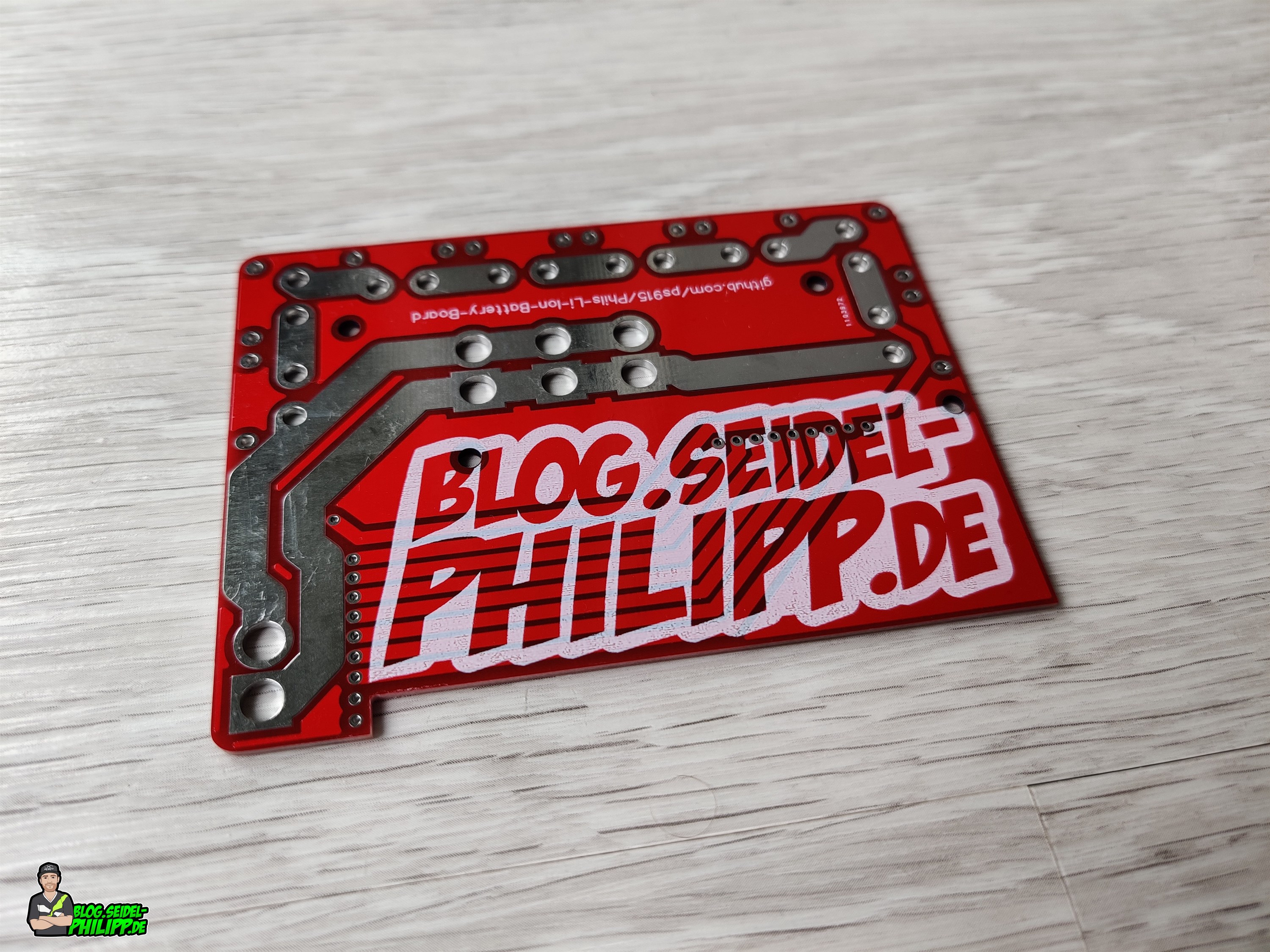
This is what the front of the PCB looks like. You can either solder on the XT60 plug directly or extend it with a cable.
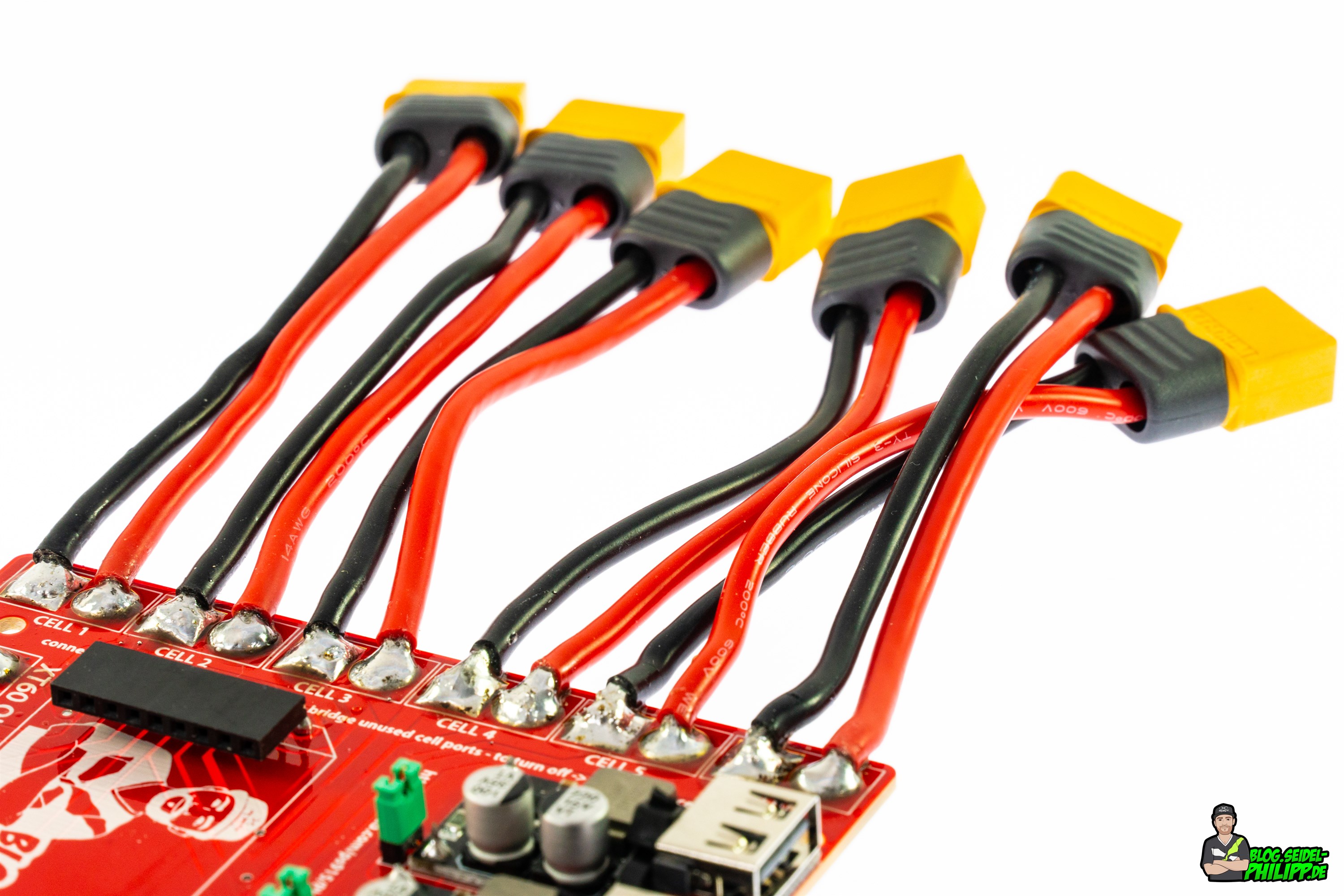
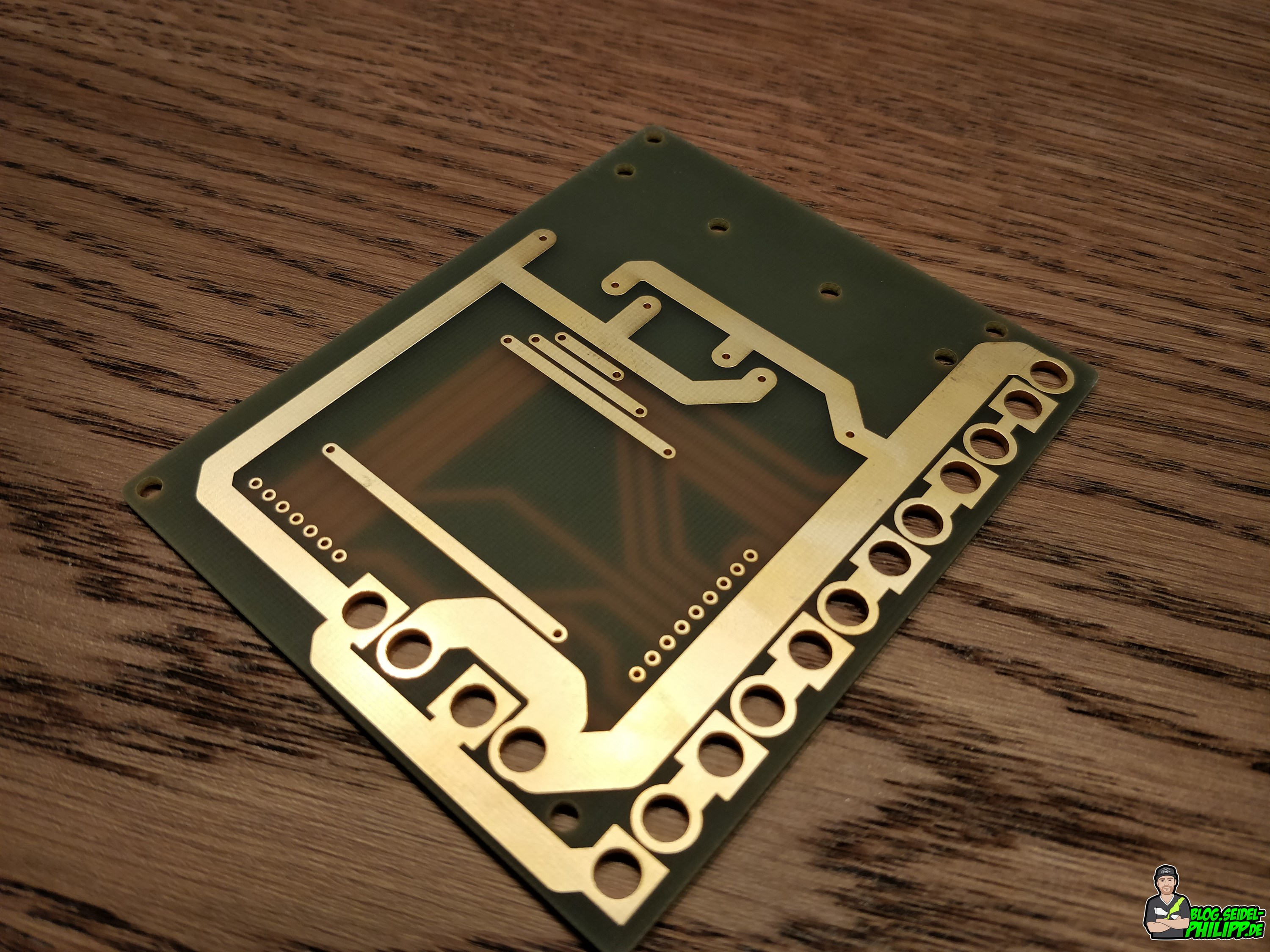
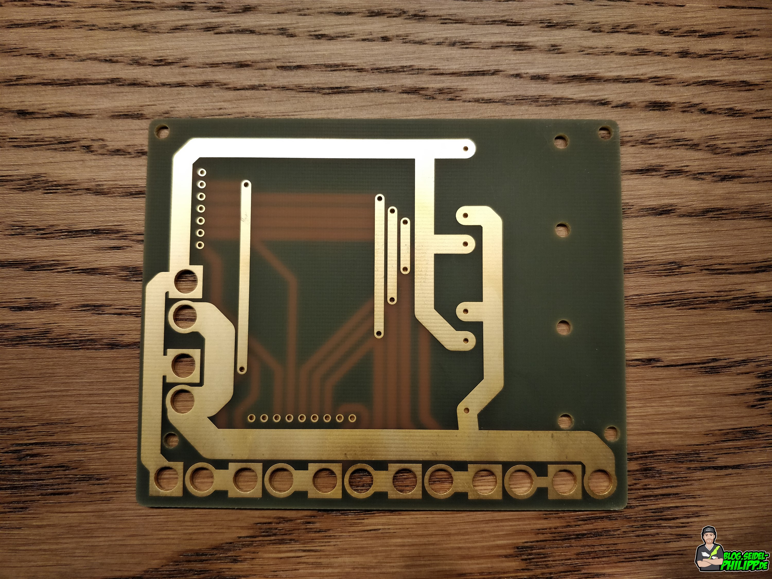
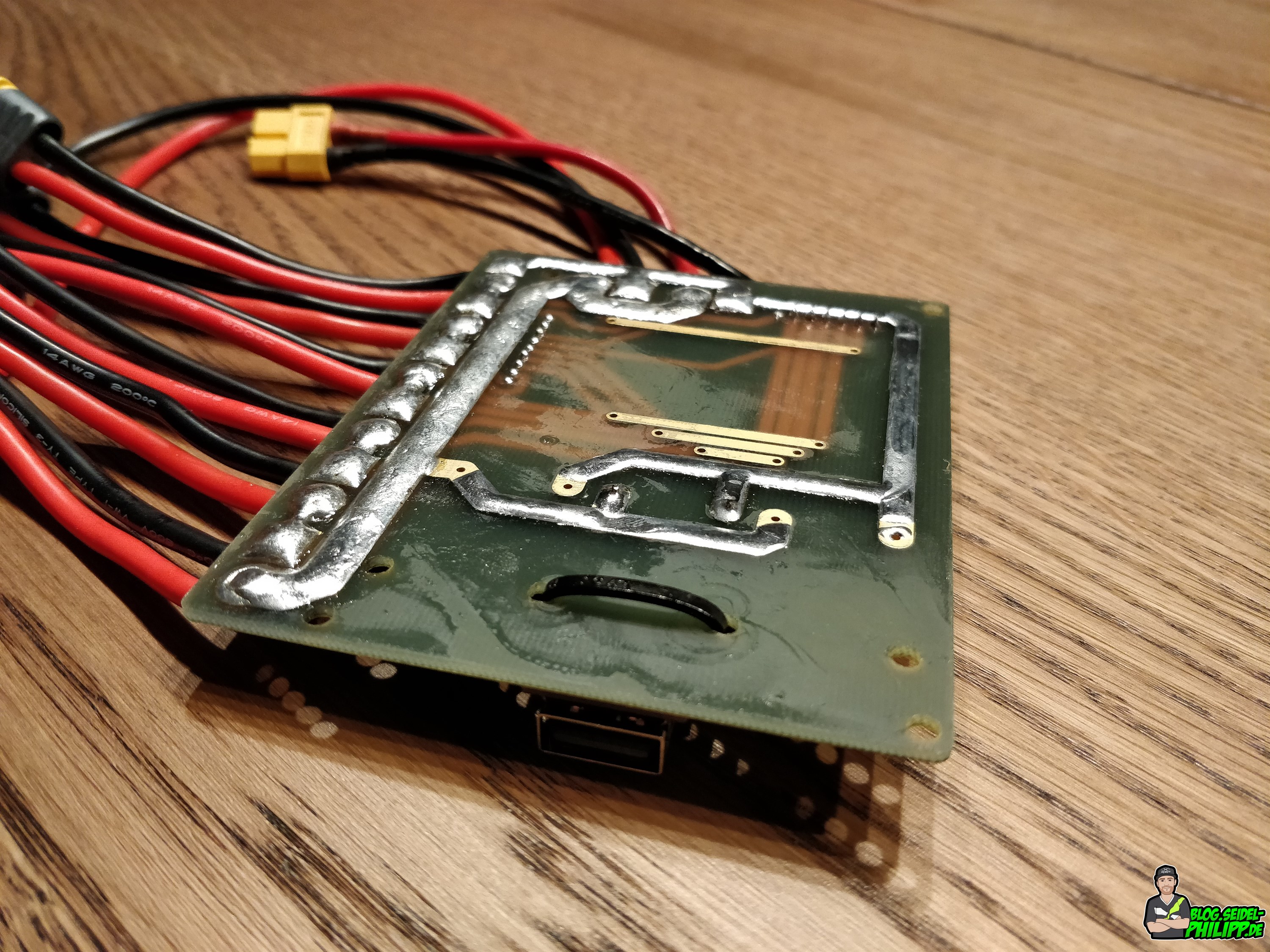
On the back I have deliberately decided against a coating. The copper tracks are exposed and should be „filled“ with sufficient solder, so that the cable cross-section increases and the PCB can withstand high current. After the solder has been applied, it should be ensured that no short circuit can occur. Ideally, the back should then be insulated with insulating tape.
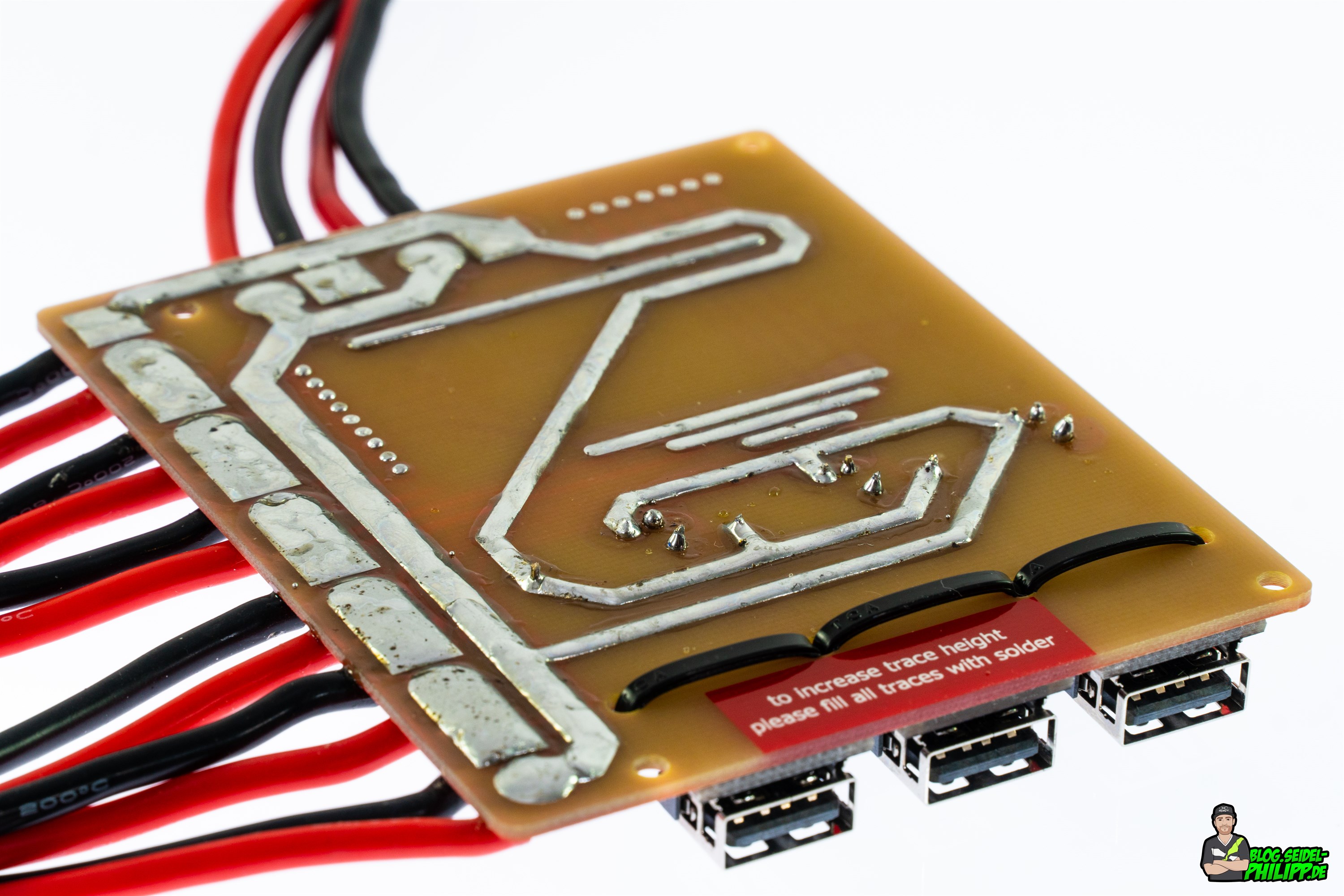
The USB modules are soldered with standard pins from RM2.54 Pin headers.
Ich habe das PCB bei www.pcbway.com bestellt. PCBWAY ist eine chinesische Firma, die auch kleine Serien kostengünstig fertigen kann. Der Versand erfolgt sehr schnell per DHL Express. Wenn du dieses PCB bestellen möchtest, habe ich hier eine Anleitung wie der Bestellprozess abläuft. In der V1.1 habe ich noch eine Kupferschicht auf der Oberseite sowie teilweise auf der Unterseite hinzugefügt, die die Wärme aufnehmen soll, falls das Board extremen Bedingungen ausgesetzt ist.
I ordered the PCB from www.pcbway.com. PCBWAY is a Chinese company that can produce small series cost-effectively. Shipping is very fast via DHL Express. If you want to order this PCB, I have an instruction how to order. In V1.1, I’ve added a layer of copper on the top and some on the bottom to absorb heat if the board is exposed to extreme conditions.
PCB assembly
Github Page: https://github.com/ps915/Phils-Li-Ion-Battery-Board
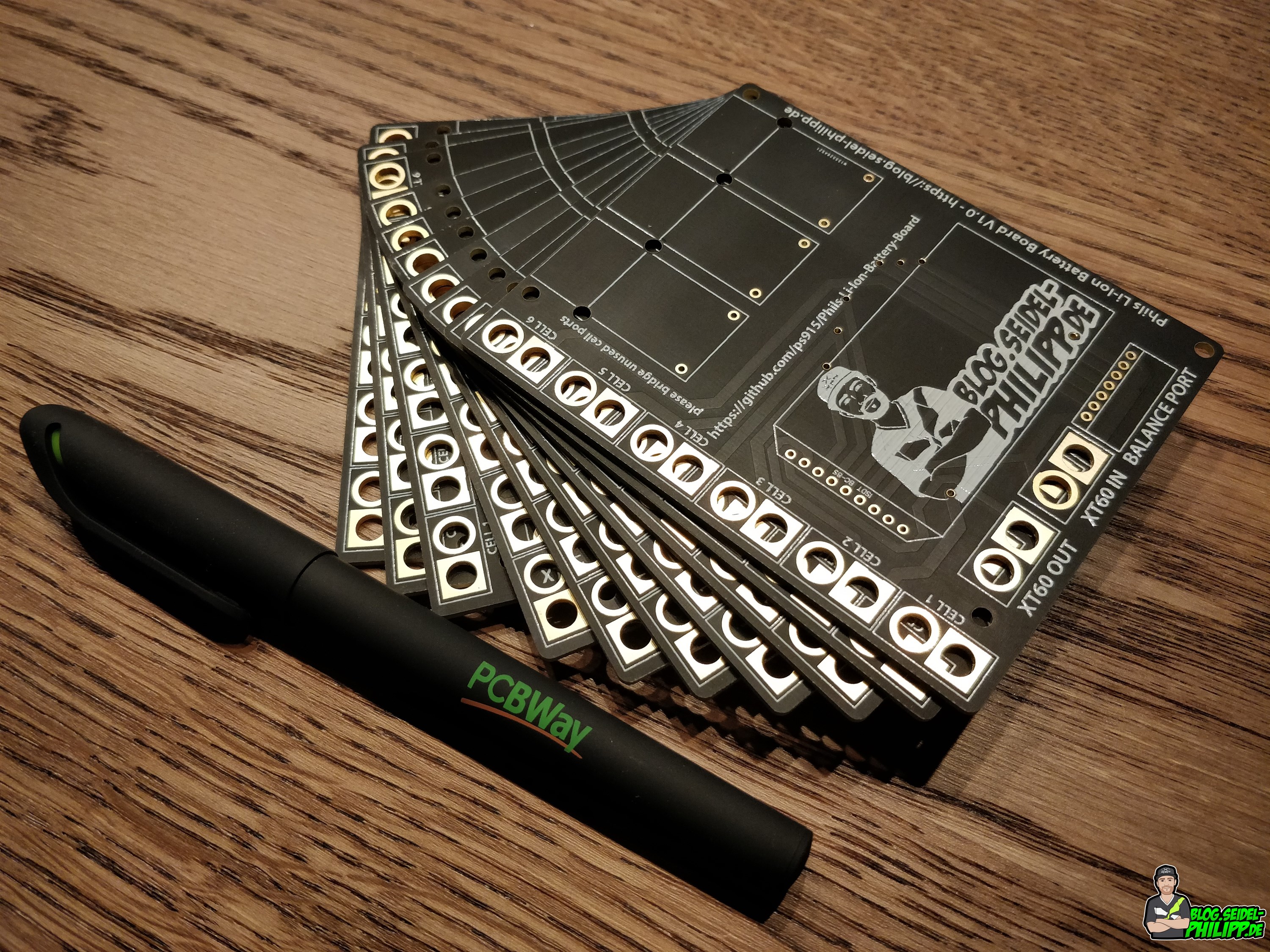
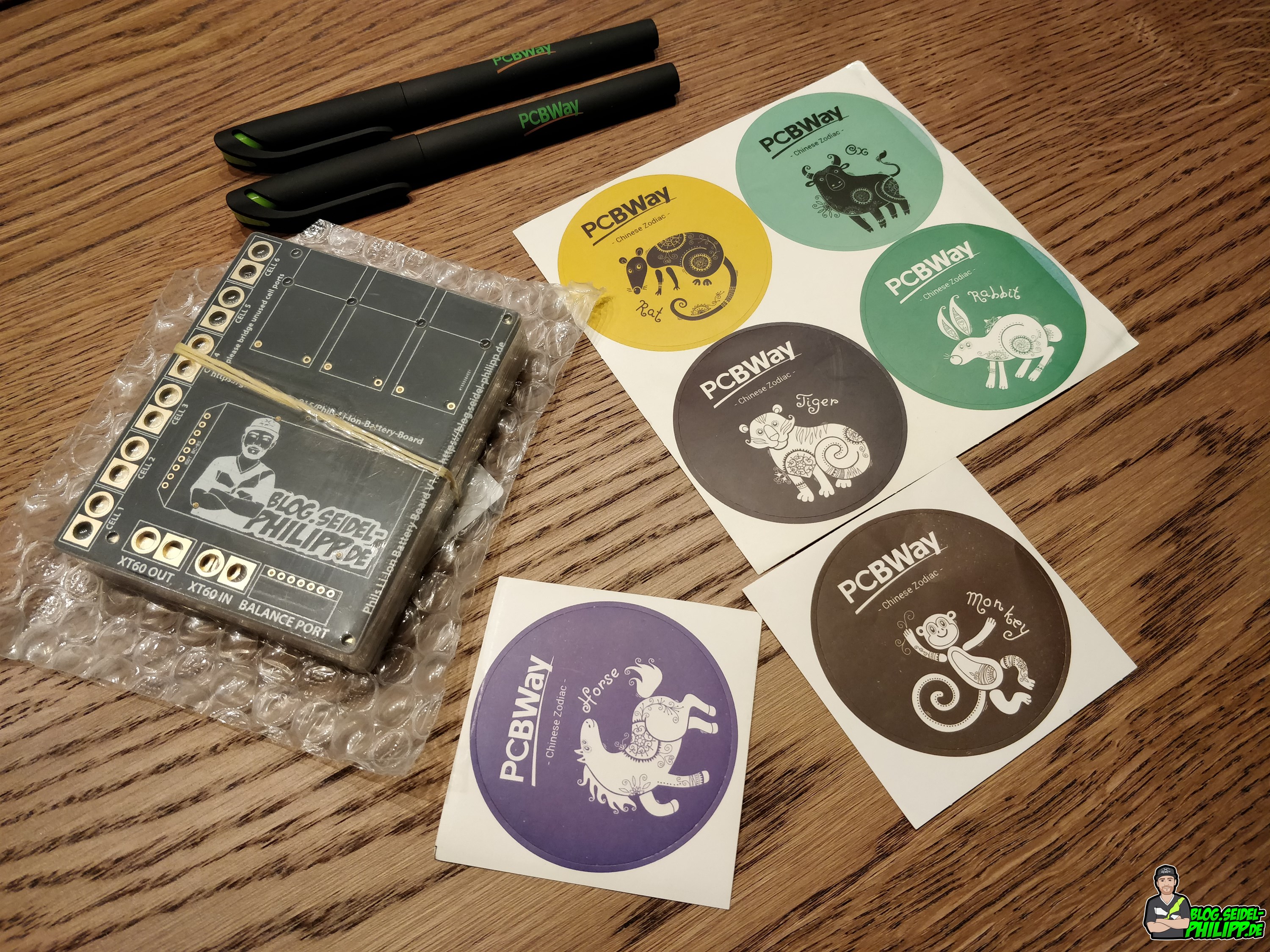
Fotos PCB V1.3
complete redesign for use of ISDT BG-8S
- supports 8S
- supports ISDT BG-8S
- angled XT60 sockets
- balance port
- 3 in/out ports
- removed USB charger due to limited space
Photos PCB V1.1
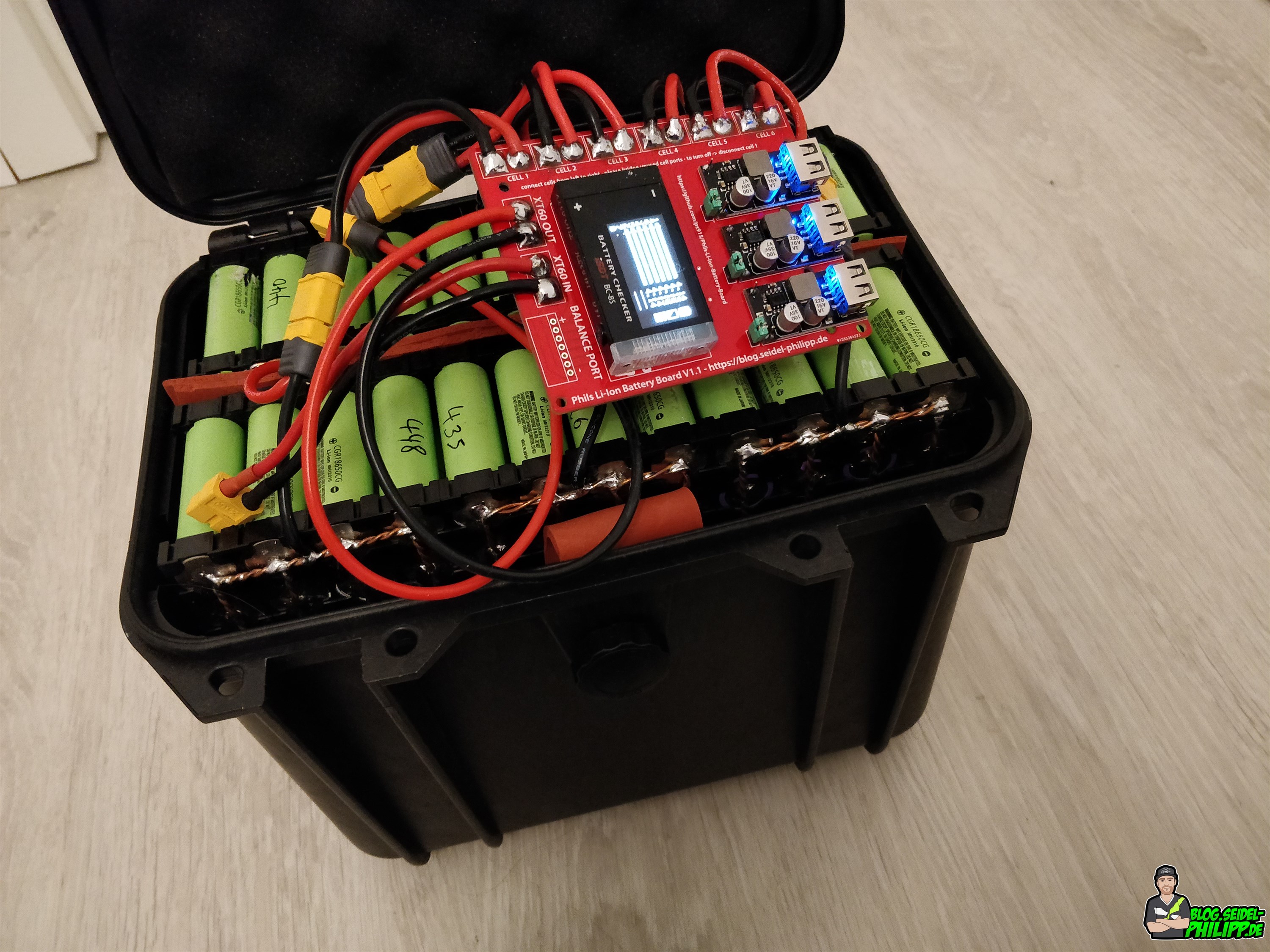
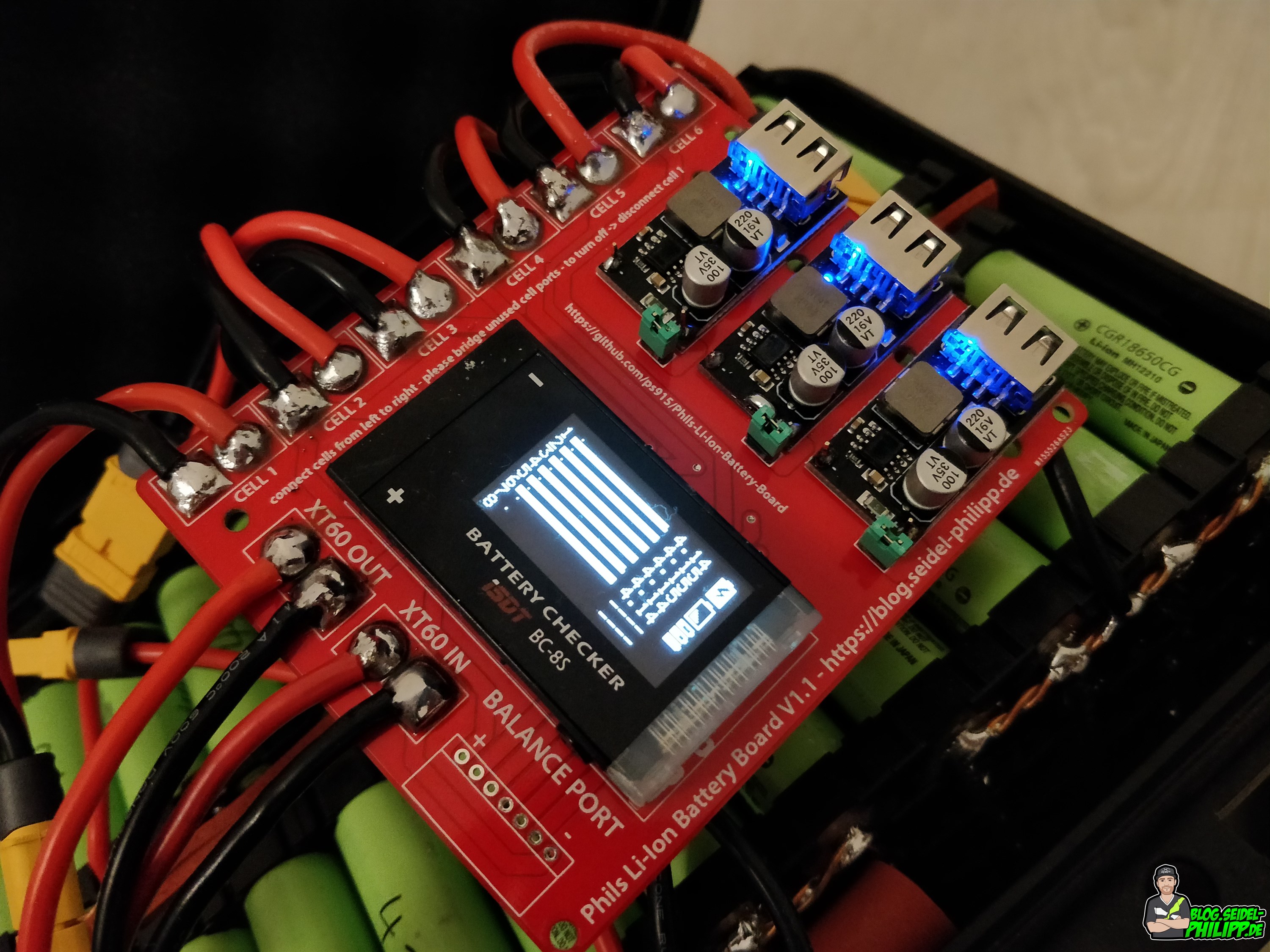
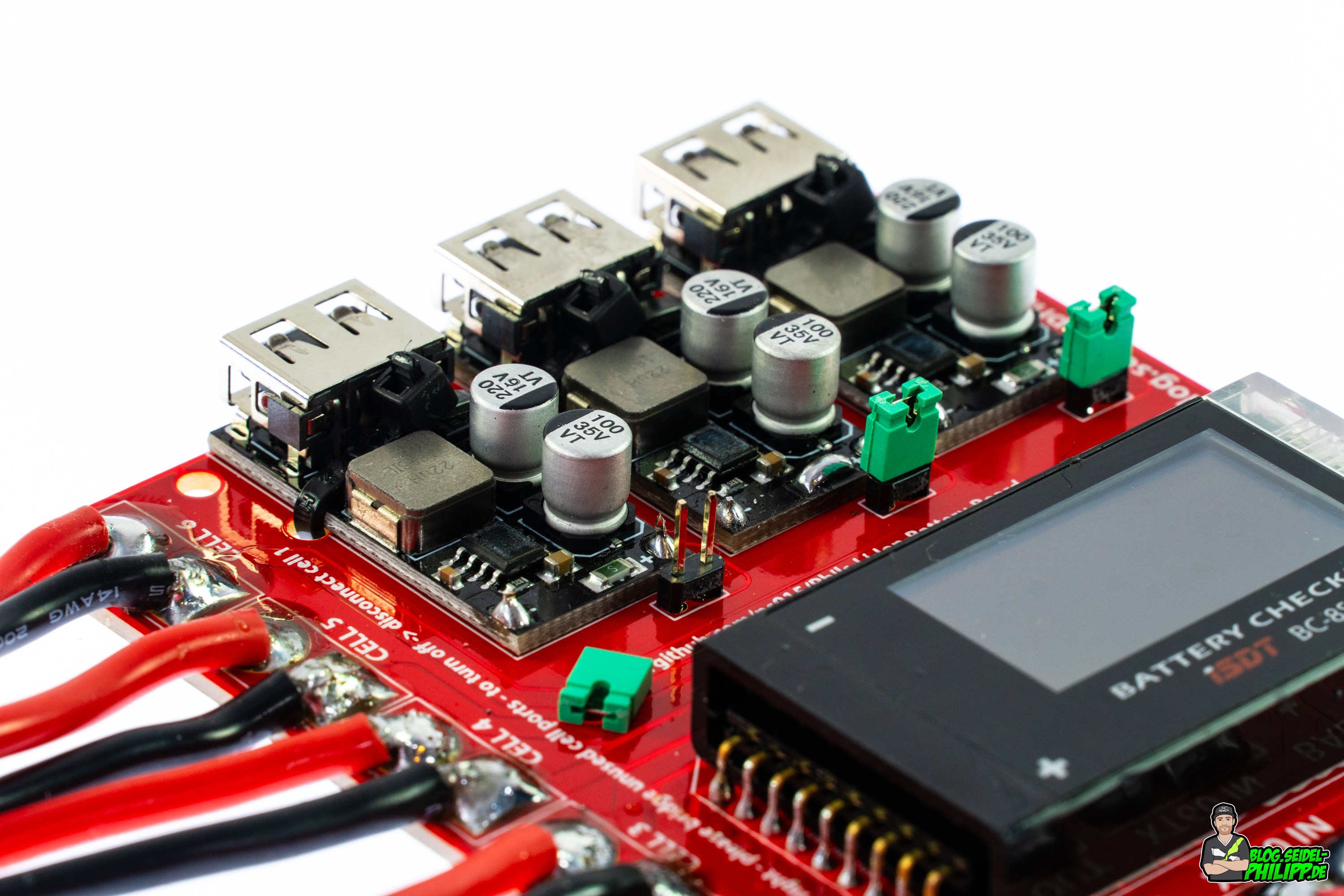
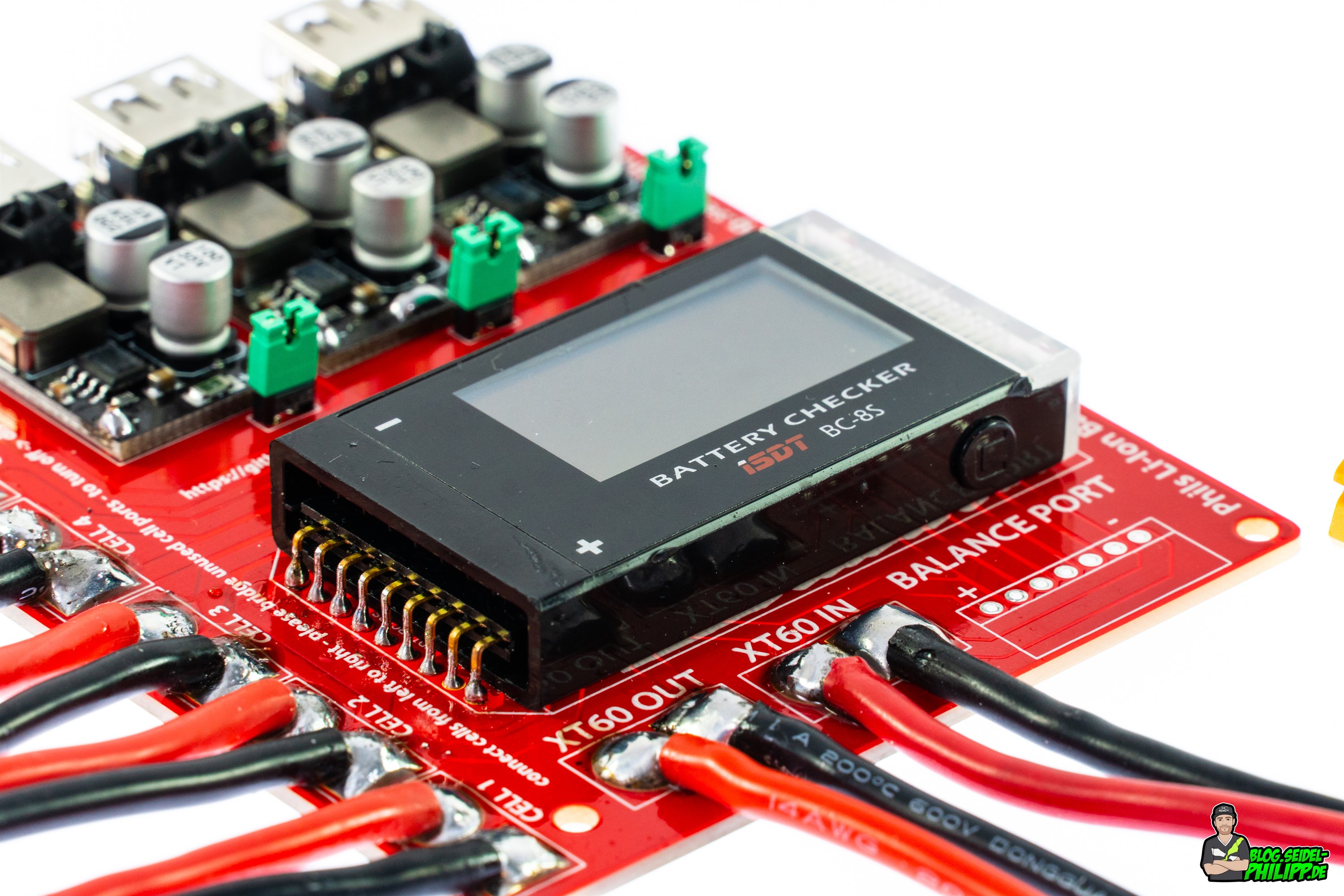
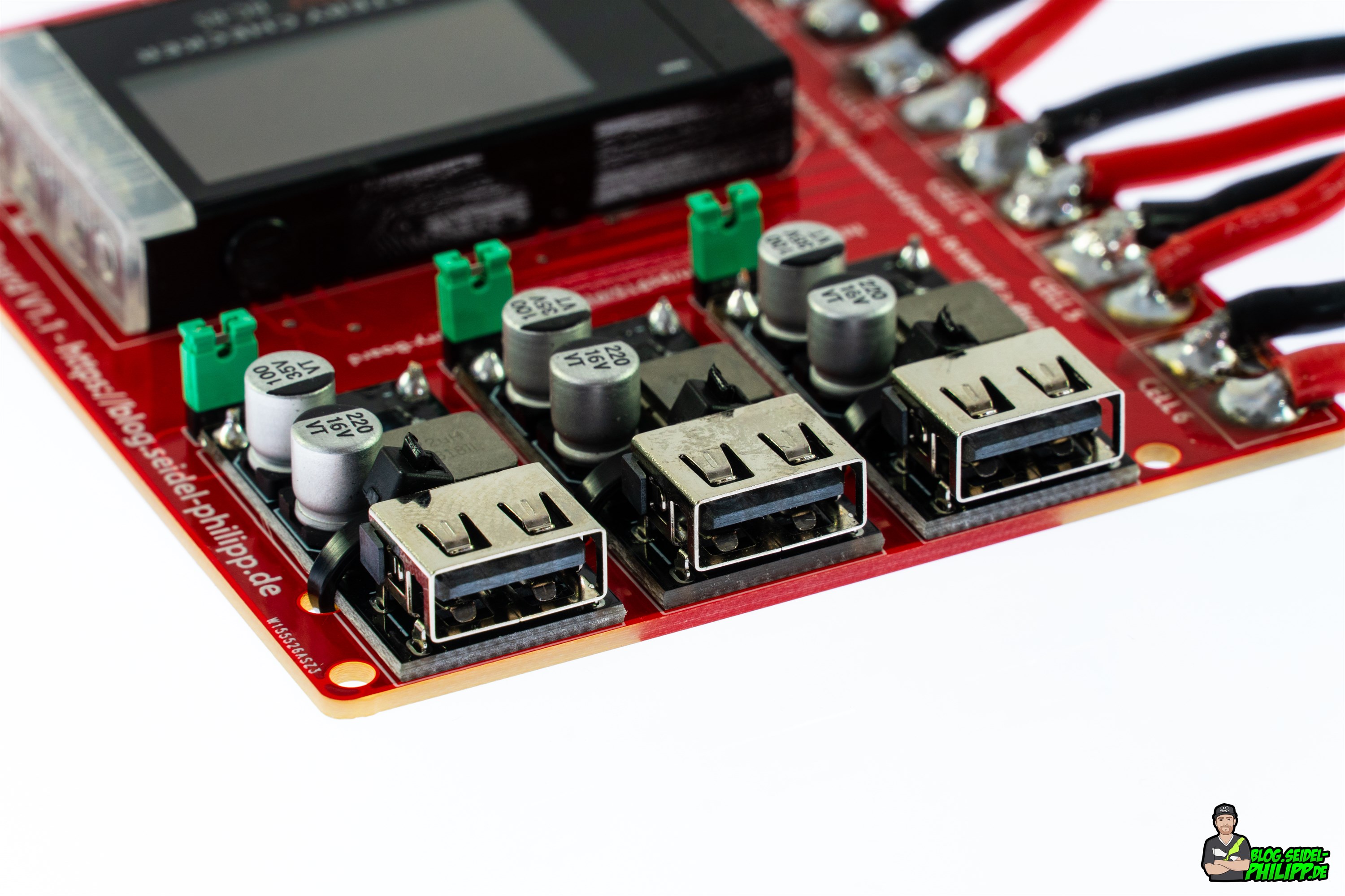
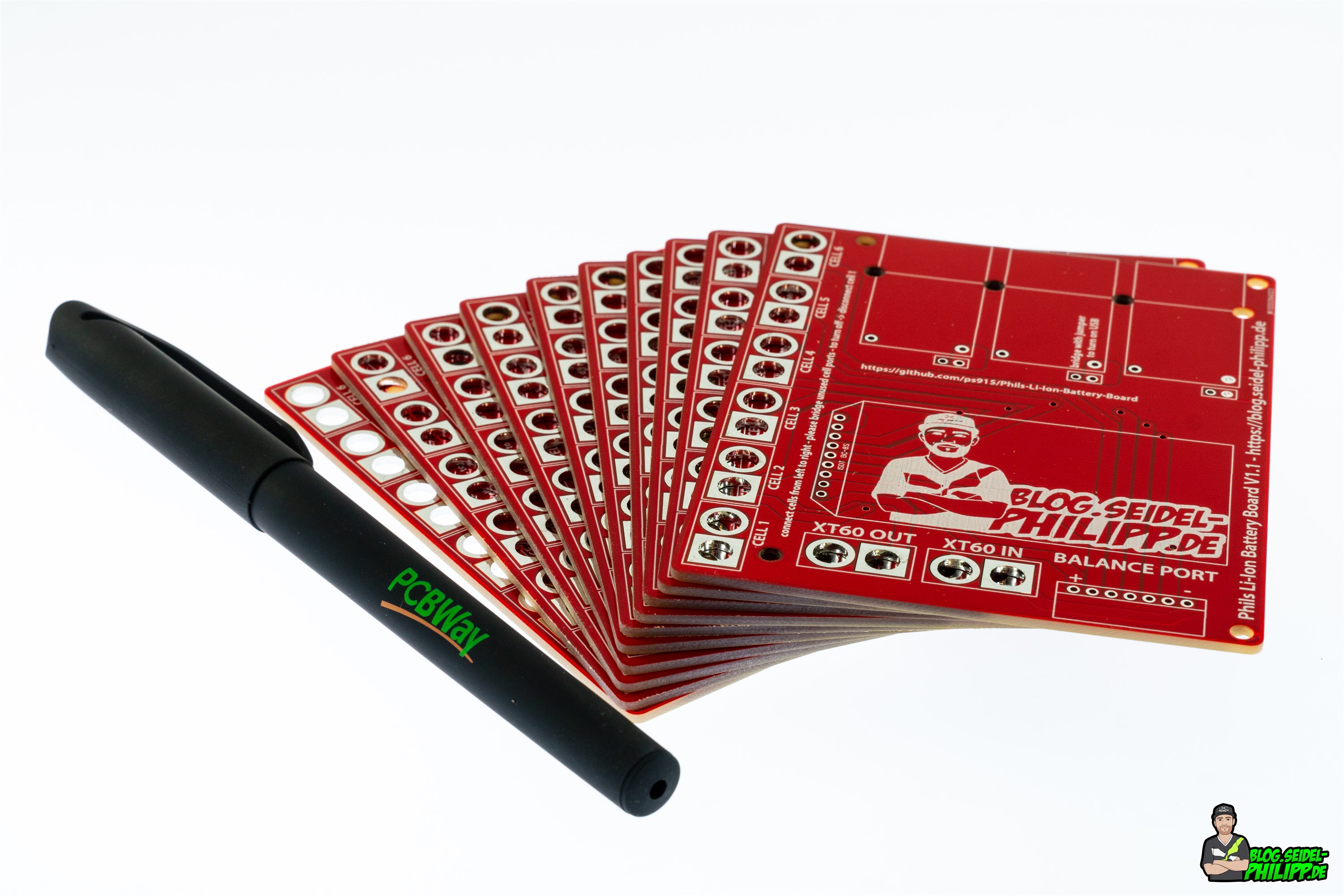
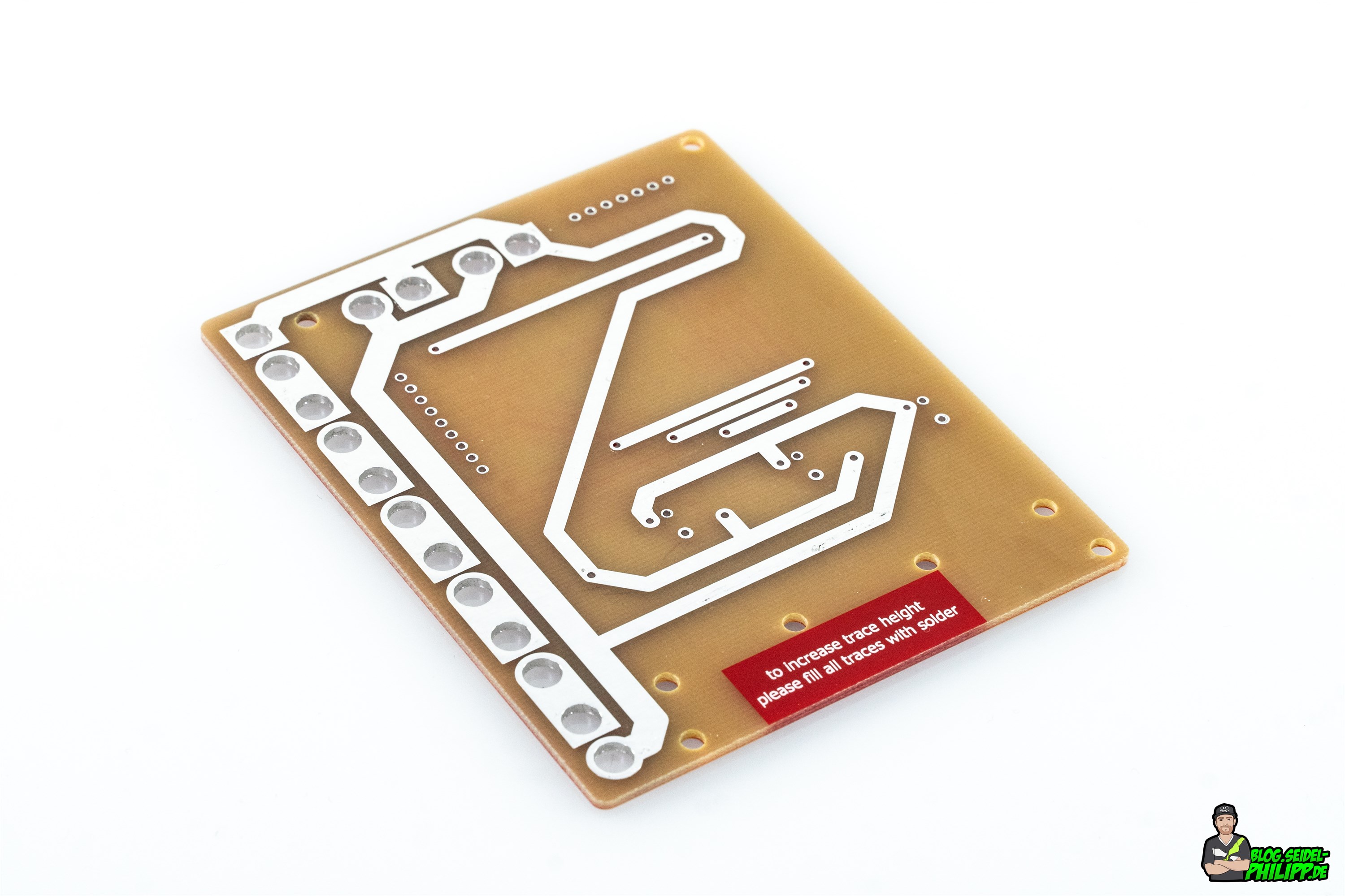
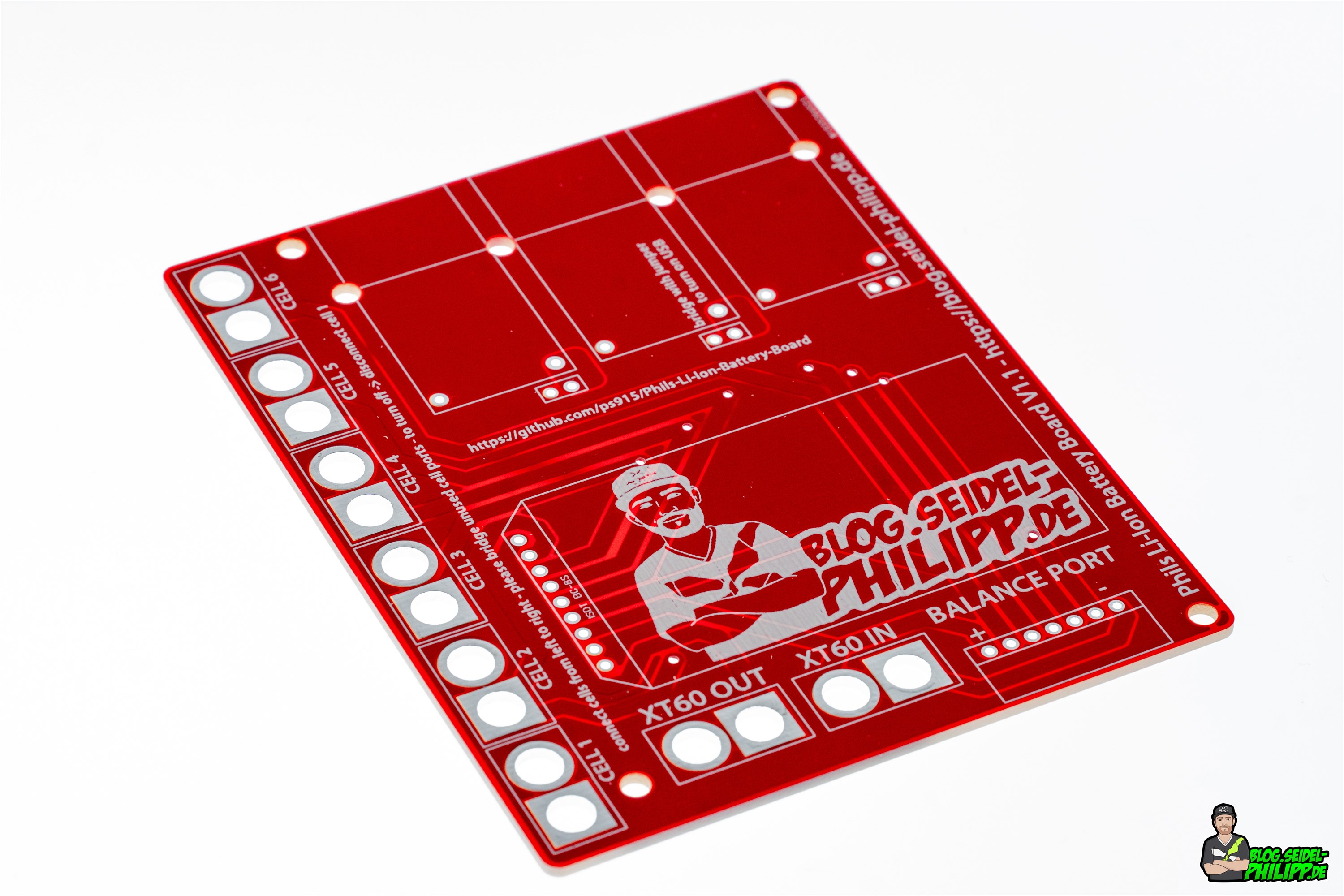
Photo PCB Prototype:

Hallo Phil,
Danke für das Project und die Opensourcestellung des PCB!
Ich habe 10 Stk der Version 1.3 in blau geordert, hätte also noch welche abzugeben. bei Interesse bitte melden.
Version 1.3 of the PCB released:

The only thing I’d do different when sorting cells, is to bin those that are below 70% of nominal capacity for that particular model. This indicates that a cell is worn down and close to the end of its life.
I have used old laptop 18650 for ebike batteries for a few years, and only the sub-70% have given me any issues. If you want extra long life, you might consider setting the limit at 75%.
Hey GalFisk,
thanks for you information! =)
Moin !
Interessantes Projekt. Aber eine Frage stellt sich mir da doch … du hast je 40 Zellen parallel und alle mit teils unterschiedlichen Kapazitäten.
Ist es dann nicht so das einige Zellen beim Entladen eher aussteigen als andere? Müsste so ein Strang dann nicht auf Dauer schnell den Geist aufgeben?
Ich würde mir nämlich gerne einen ähnlichen Akku bauen (etwas kleiner) zum Nachladen am Flugplatz …
btw: Hättest du noch eine Platine zu verkaufen?
Grüße Dominik
Hey Dominik,
Ja in der Tat haben alle Zellen eine etwas andere Kapazität. Allerdings habe ich die Zellen ja vorher nach Kapazität sortiert und nur solche parallel zusammen geschaltet, welche nahezu die selbe Kapazität haben. Somit verteilt sich die Last ganz gut.
Wenn du natürlich 30 Zellen mit 3000mAh und eine mit 1000mAh verbaust, wir diese eine Zelle wesentlich höher beansprucht, sodass es deutlich wahrscheinlicher ist, dass diese eine Zelle als erstes ausfällt oder auf dauer kaputt gehen wird.
Ich habe noch ein PCB abzugeben, schreib mir einfach einen E-Mail oder kontaktiere mich via Facebook!
Gruß,
Phil
Hey,
Interessanter Artikel! Kannst du vielleicht ein bisschen erklären, wo du die ganzen Zellen her hast und wieviel Geld dich alles zusammen gekostet hat.
Gruß Tim
Hey Tim,
ich habe sie von eBay oder durch Aufrufe in der Community bekommen. Ebenso kannst du lokale Fahrradhändler (für E-Bike Akkus) oder PC-Reparatur Werkstätten aufsuchen, die haben Massenweise solche Akkus liegen.
Gruß,
Phil