
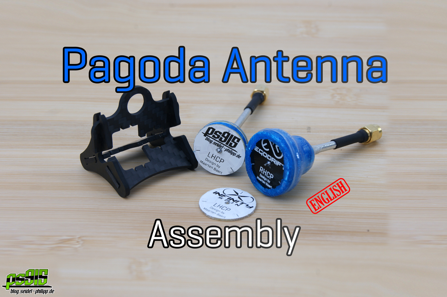
Pagoda FPV Antenna – Assembly
![]()
This article is about assembling the popular pagoda FPV antenna from Maarten Baert.
If you want to build the antenna yourself, here is a guide on how to order the boards yourself.
Inhaltsverzeichnis
What we need
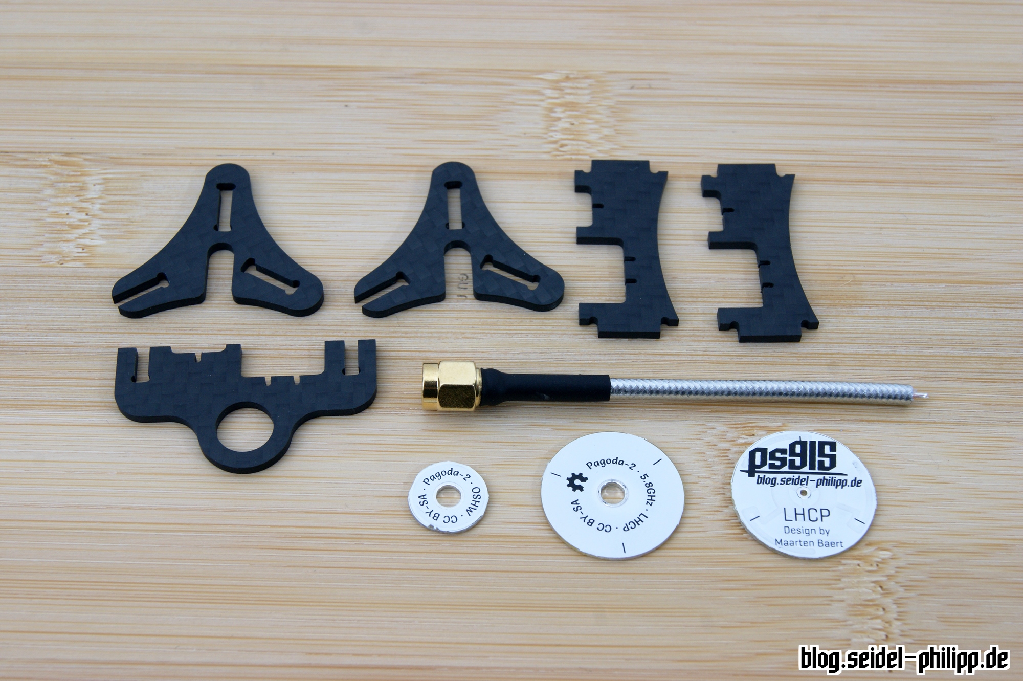
- Soldering-Aid from www.carbon-posten.de (GFK)
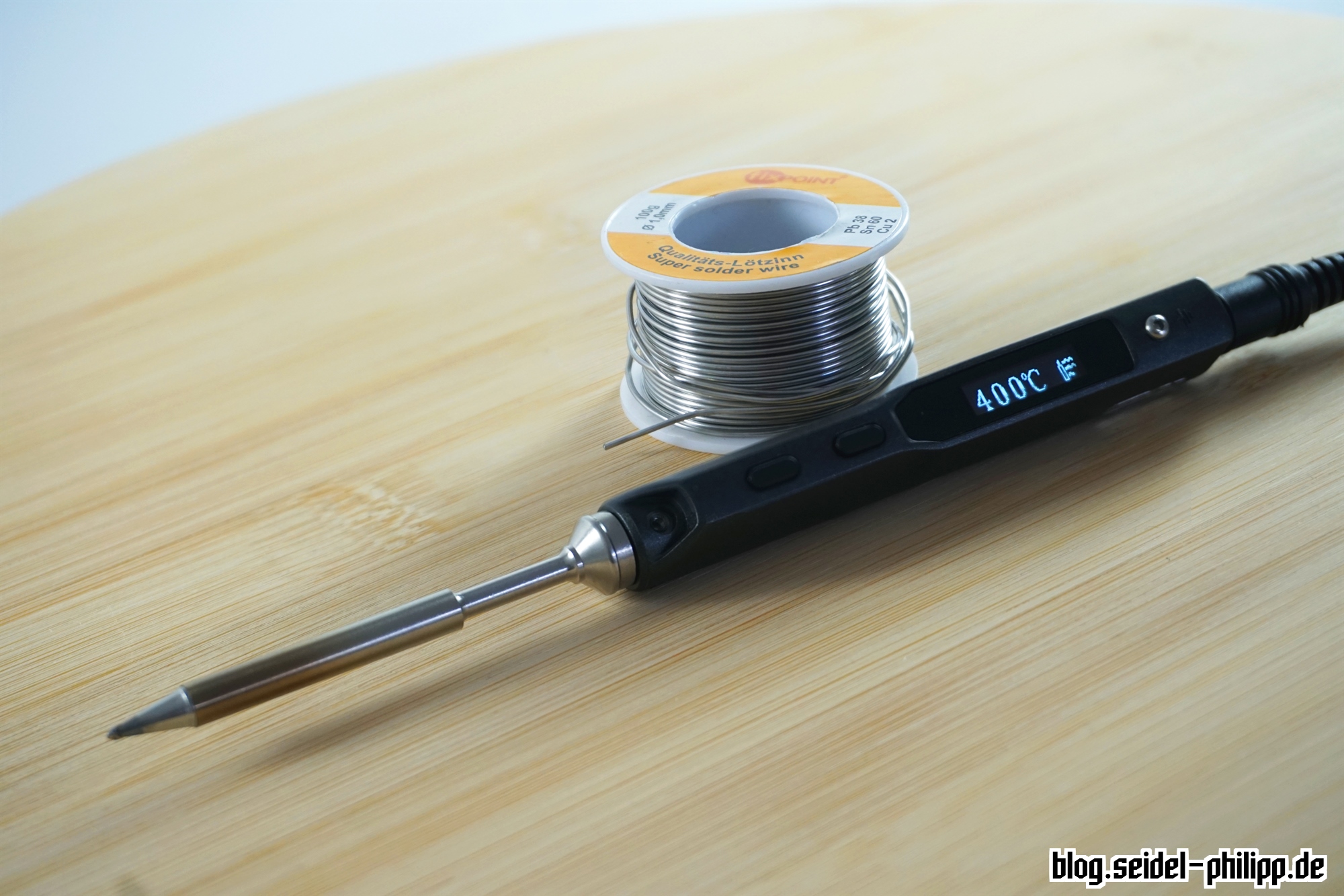
- Soldering Iron(e.g. TS100) + solder (e.g. FixPoint)
- Pagoda PCBs
- RG402 Coax cable 1M, 3M, 1M Banggood
- SMA sockets for RG402 cable or alternatively finished RG402 cable (cut -> aaaaaannndd tadaa.. 2 finished antenna cable =) )
- Optional: Diomindfile or sandpaper
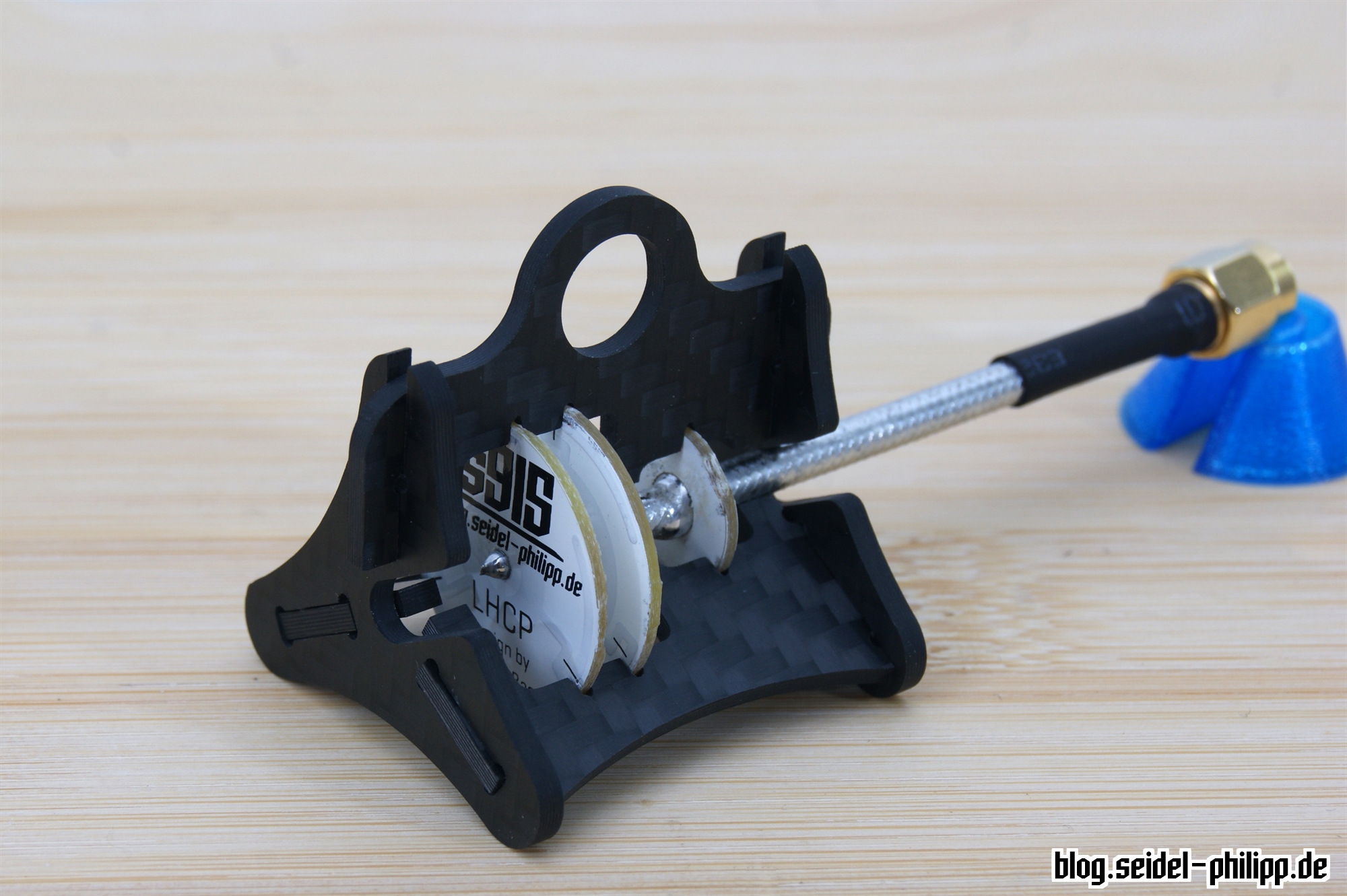
The Pagoda Soldering-Aid
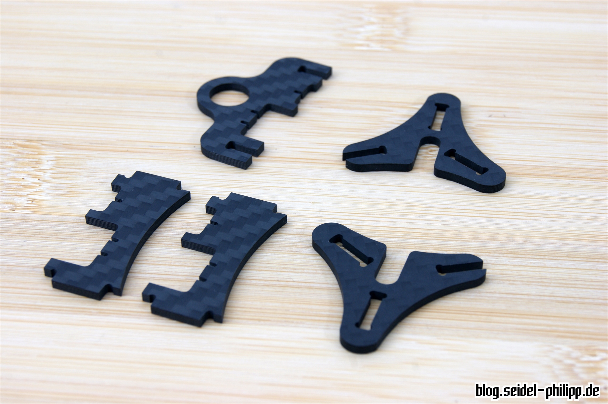
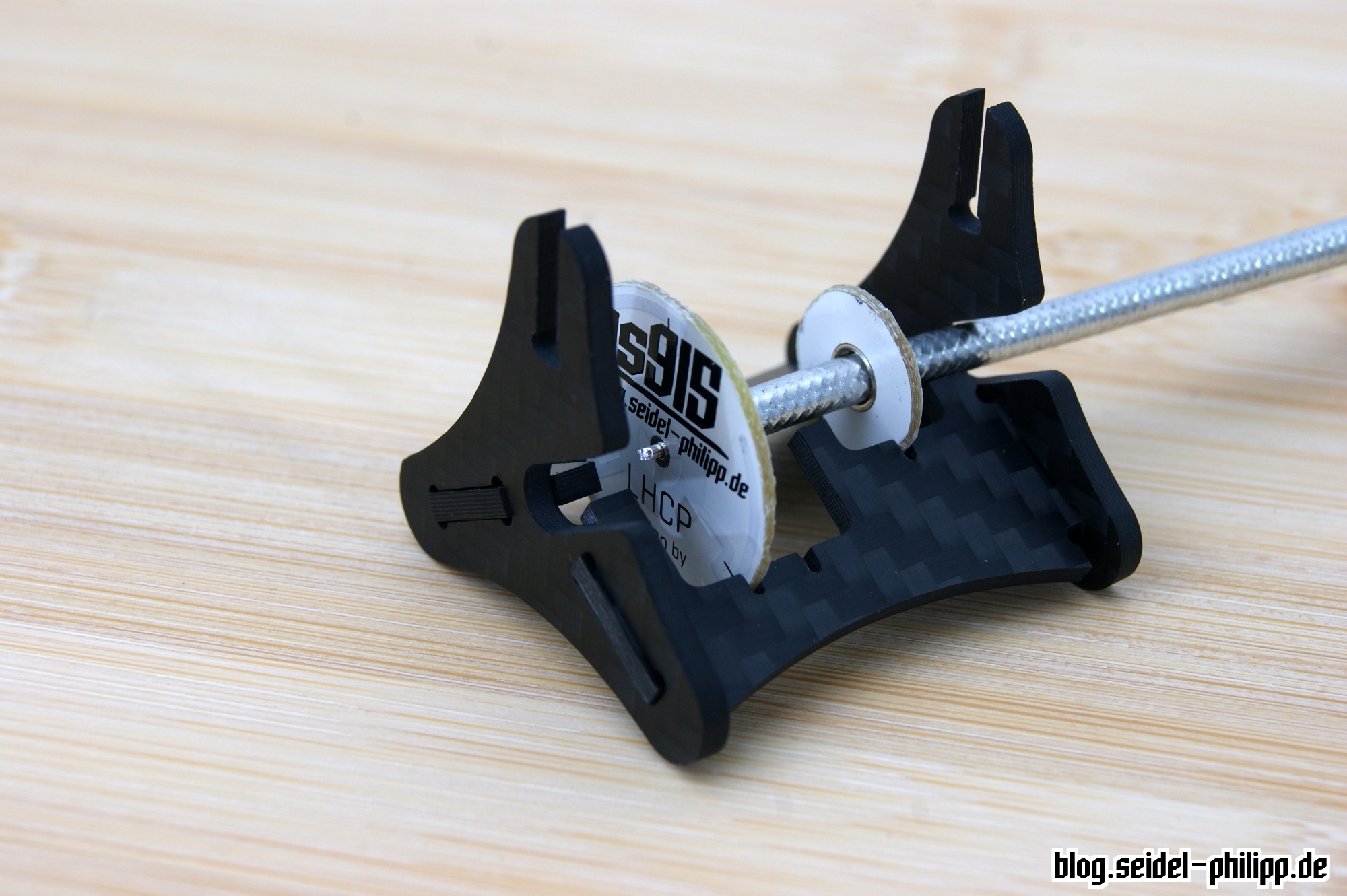
Together with Klaus Krieber (CFK God and designer of the first monocoque frame), we designed the following soldering aid. All boards are aligned exactly parallel to each other at 3 points. With this soldering aid even antenna cables with already soldered SMA connectors can be used. We arranged the production of these parts with carbon-posten.de, so that we can invest our time better in our projects. There may be a more favorable variant of glass fiber or lasered acrylic. These have to be tested.
Prepare the soldering-aid
The PCBs have a thickness of 1mm. The slots are also milled to 1mm, but the boards may slide hard into the slots. This can vary from manufacturer to manufacturer.
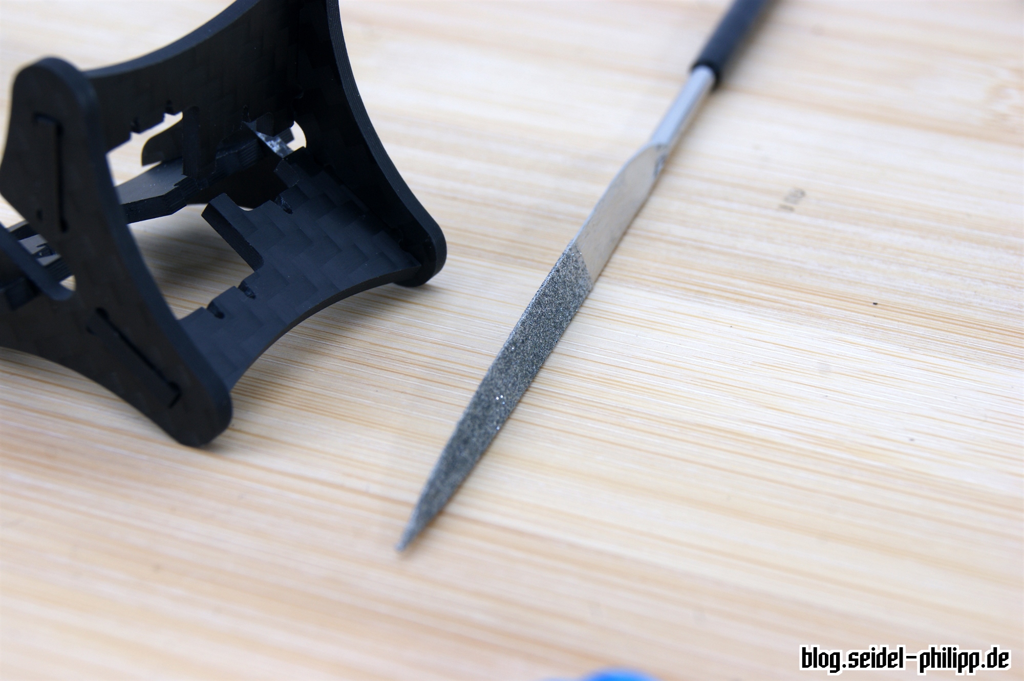
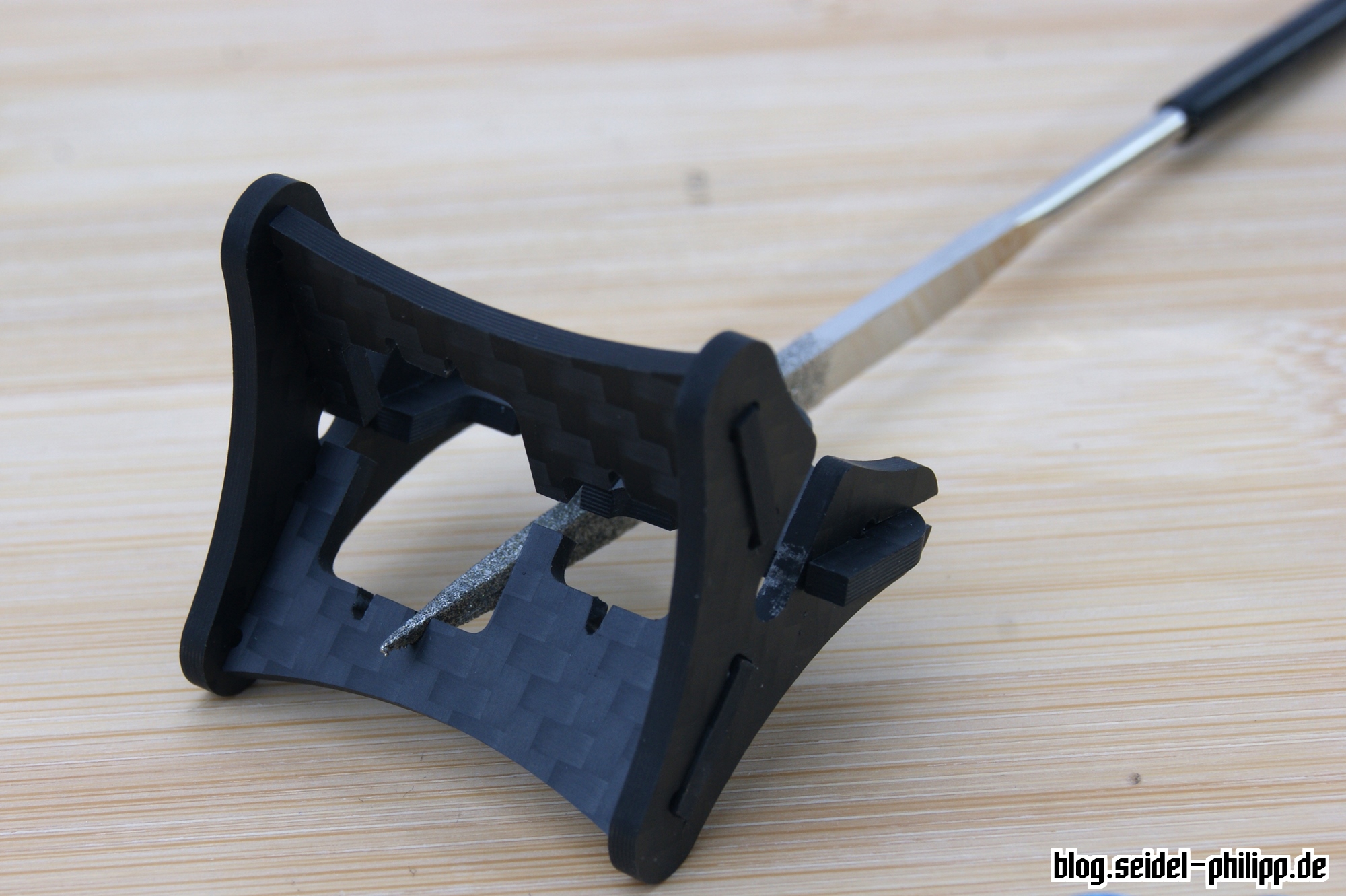

In addition, there may be minimal deviations when the cutting tools are used a lot. Nevertheless, the whole soldering-aid is milled extremely precisely and requires only rework when the PCBs slide to hard into the slots. With a diamond file or fine abrasive paper, the slots can be expanded minimally. The depth of the slots shouldn’t be changed.
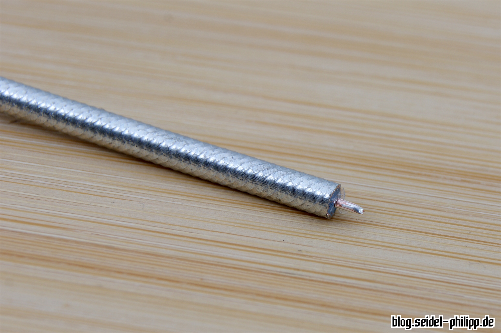
Prepare the coax cable
The cable should be as straight as possible. With a knife you separate 2-3mm outer jacket as well as insulation.

Important: The cut should be straight all around the cable so that the first board is as planar as possible.
solder the Pagoda FPV Antenna
Now lets get to solder the antenna. Please note that there are two different procedures depending on whether you have a cable with a SMA plug, or not.
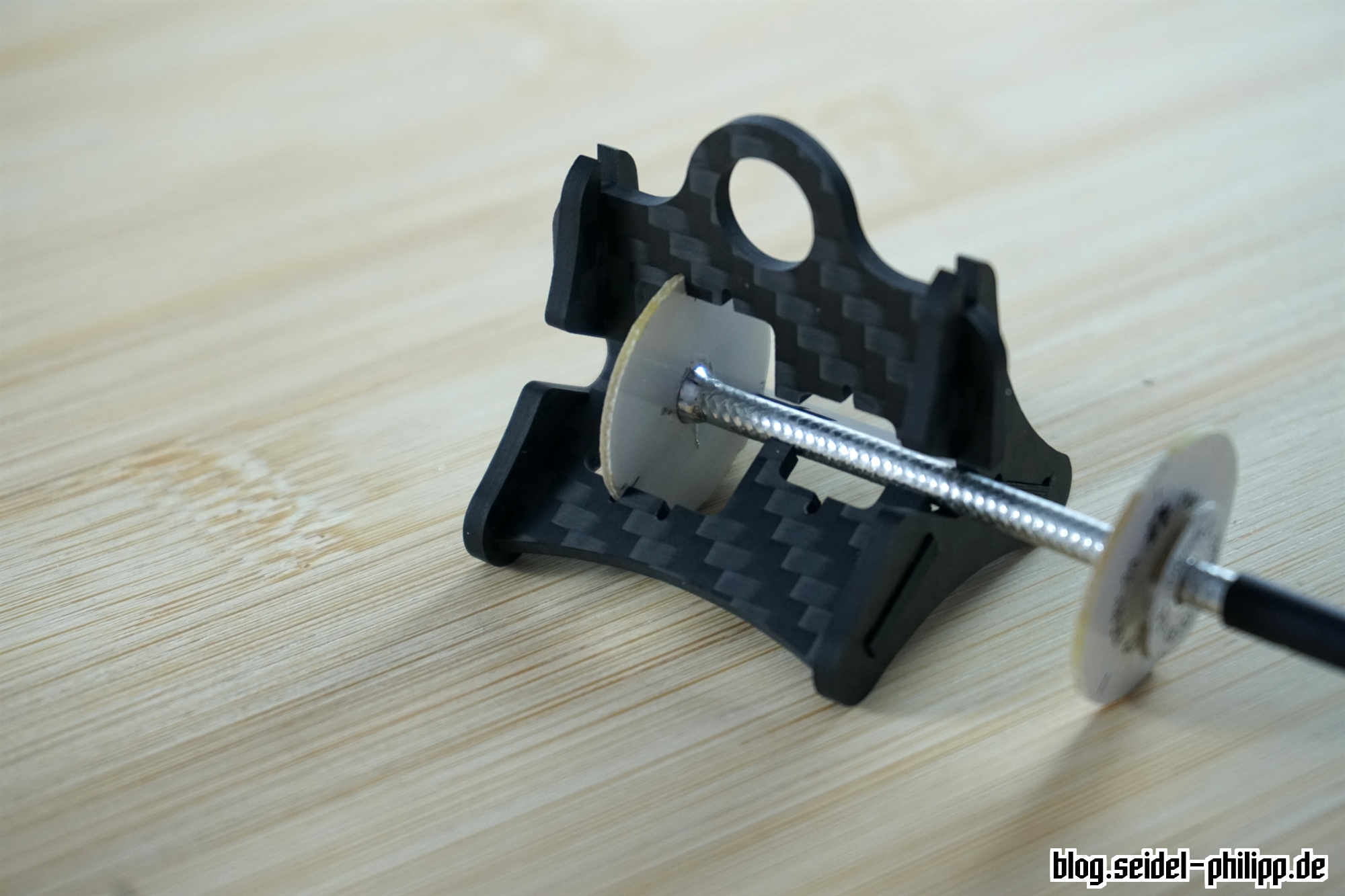
insert PCB 1 and 3
As a first step, we insert PCB 1 and 3 when we want to solder the SMA plug afterwords. If the SMA plug is already soldered, we must now slide all 3 PCBs correctly on the coaxial cable and only insert PCB 1 into the soldering-aid.
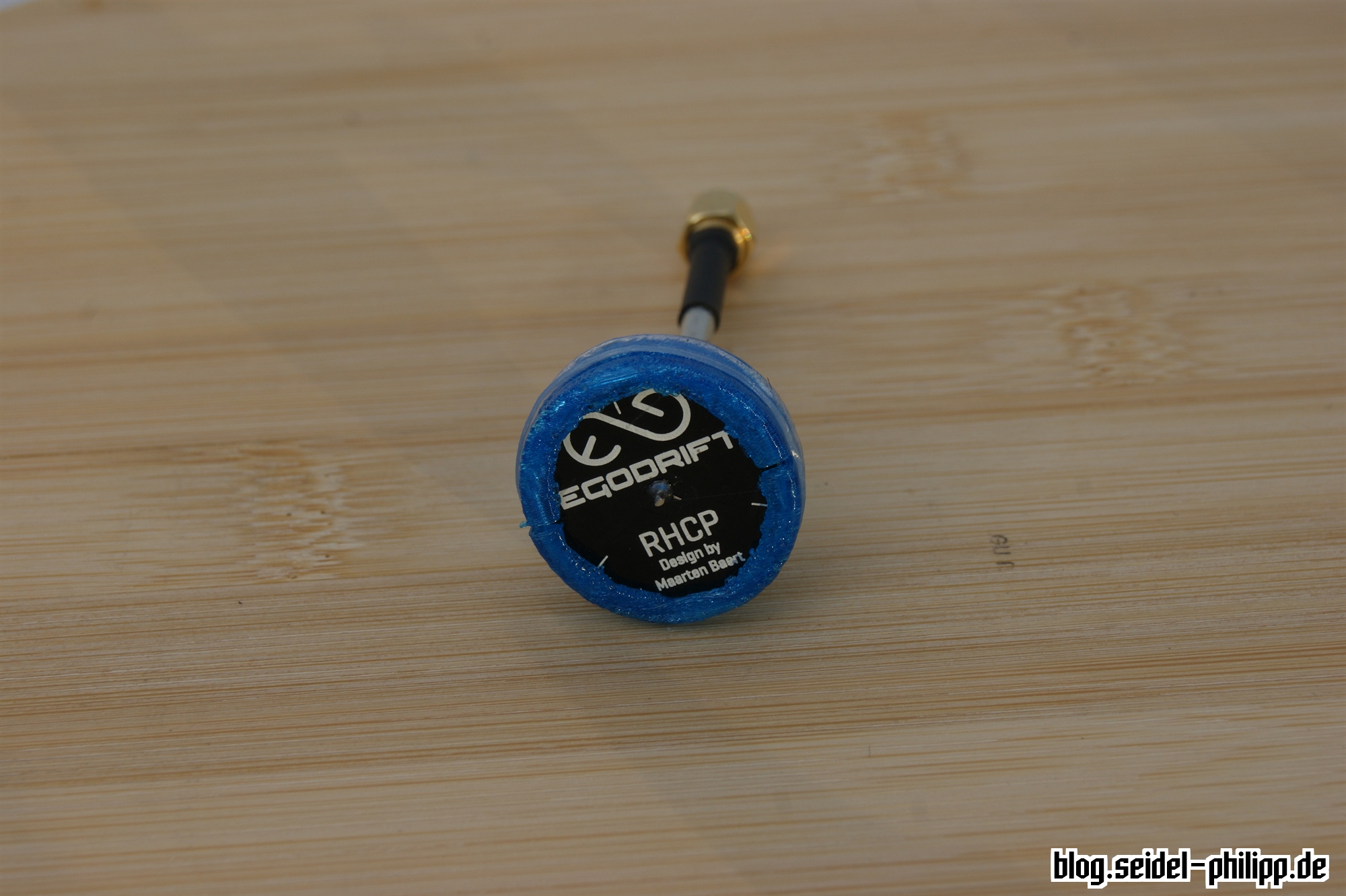
Important: The font or the logo of the first board is visible when you look at the top of the Pagoda FPV antenna. The two following boards are aligned onto the coaxial cable, so that the text is in the direction of the antenna end / SMA connector.
Without SMA plug
With SMA plug

solder PCB 1
Now we solder the first PCB. It does not matter whether you solder the signal on the top or the ground on the bottom first.
insert PCB 1 and 3
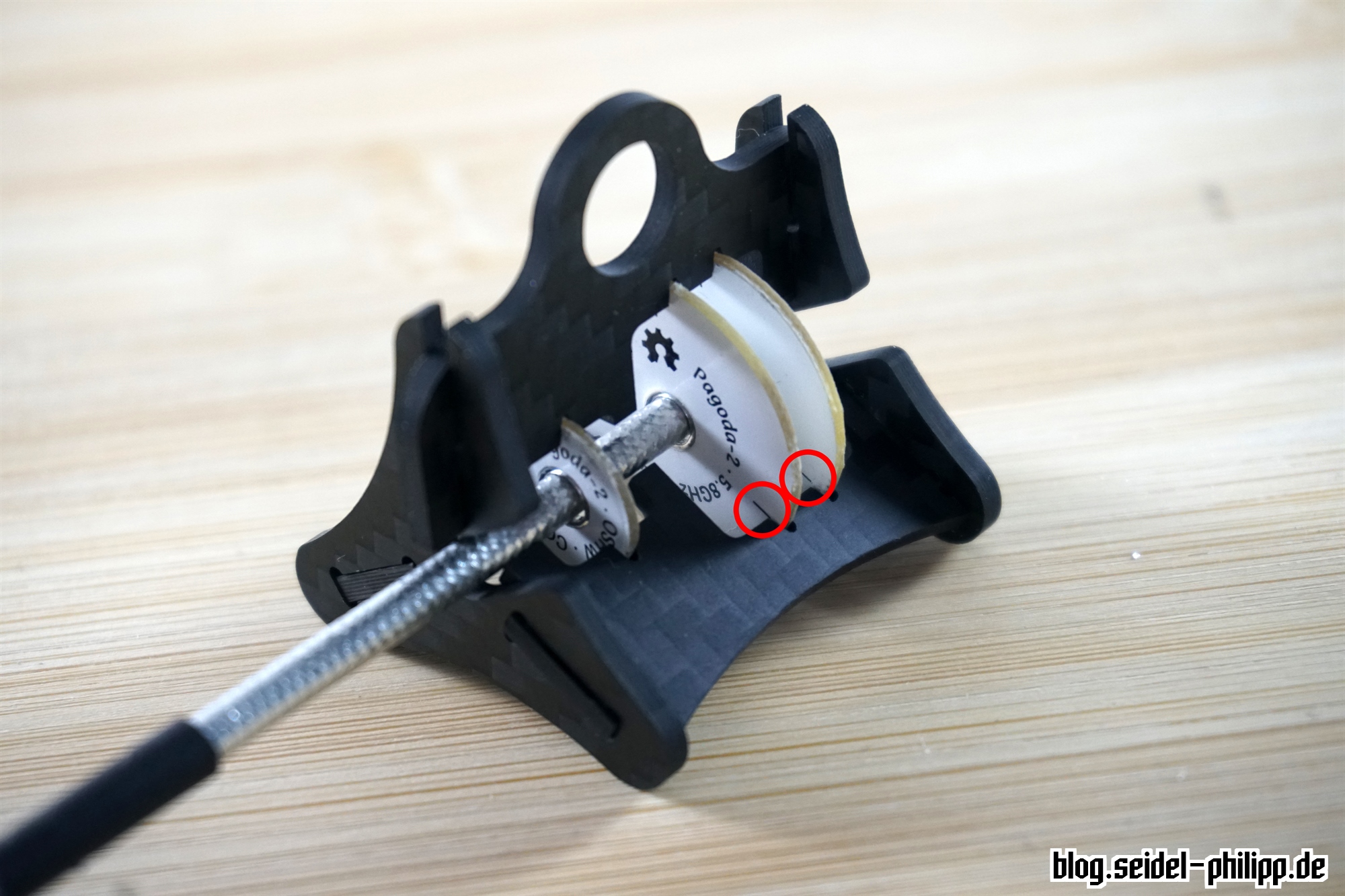
Now you can insert PCB 2 and 3. Please ensure that the font is correct as described above.
Important: On the PCB 1 and 2 you will find 3 lines on both sides. Make sure that they lie exactly one above the other when you solder them.
solder PCB 2 and 3
Now you can solder all the remaining PCBs together. PCB 2 (the middle) can be soldered from one side only. However, you can heat the soldering joint from the bottom side until the soldering flux flows to the other side. Please use as little solder as possible and try to make a small bead (not like me 😉 )
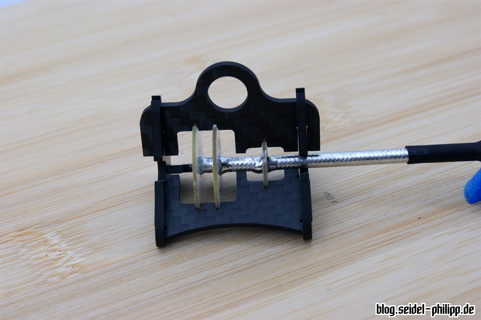
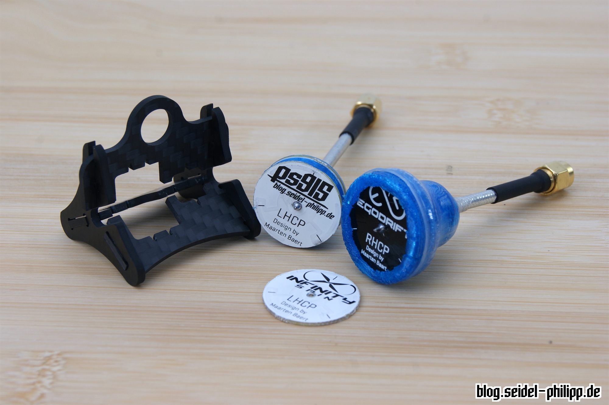
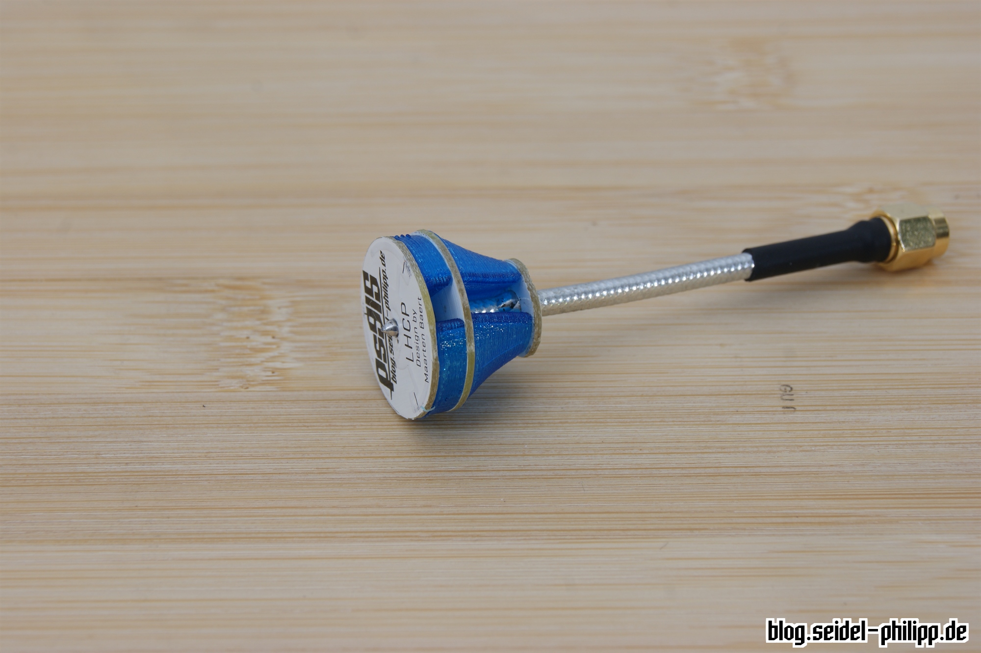
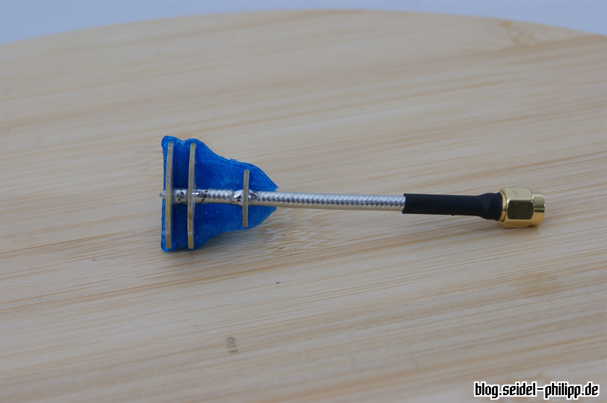
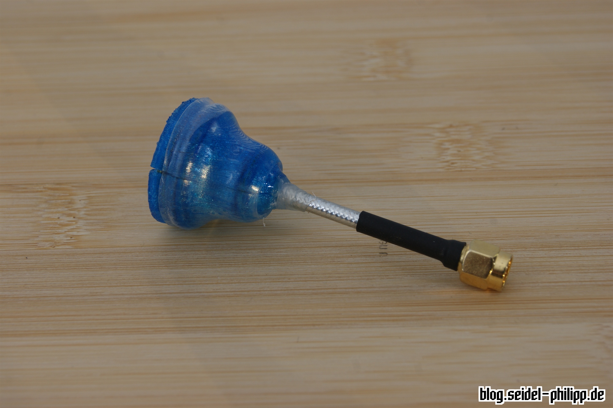
Your Pagoda FPV antenna should look like this. You can now dismantle the soldering-aid.
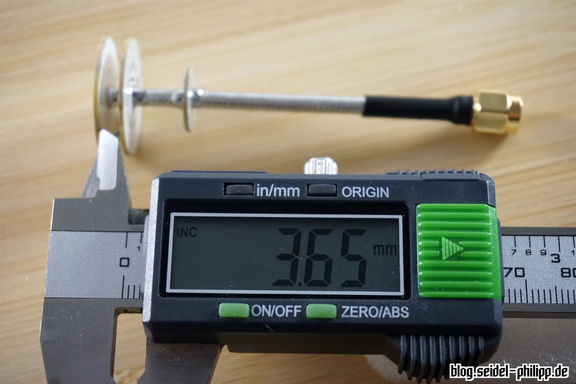
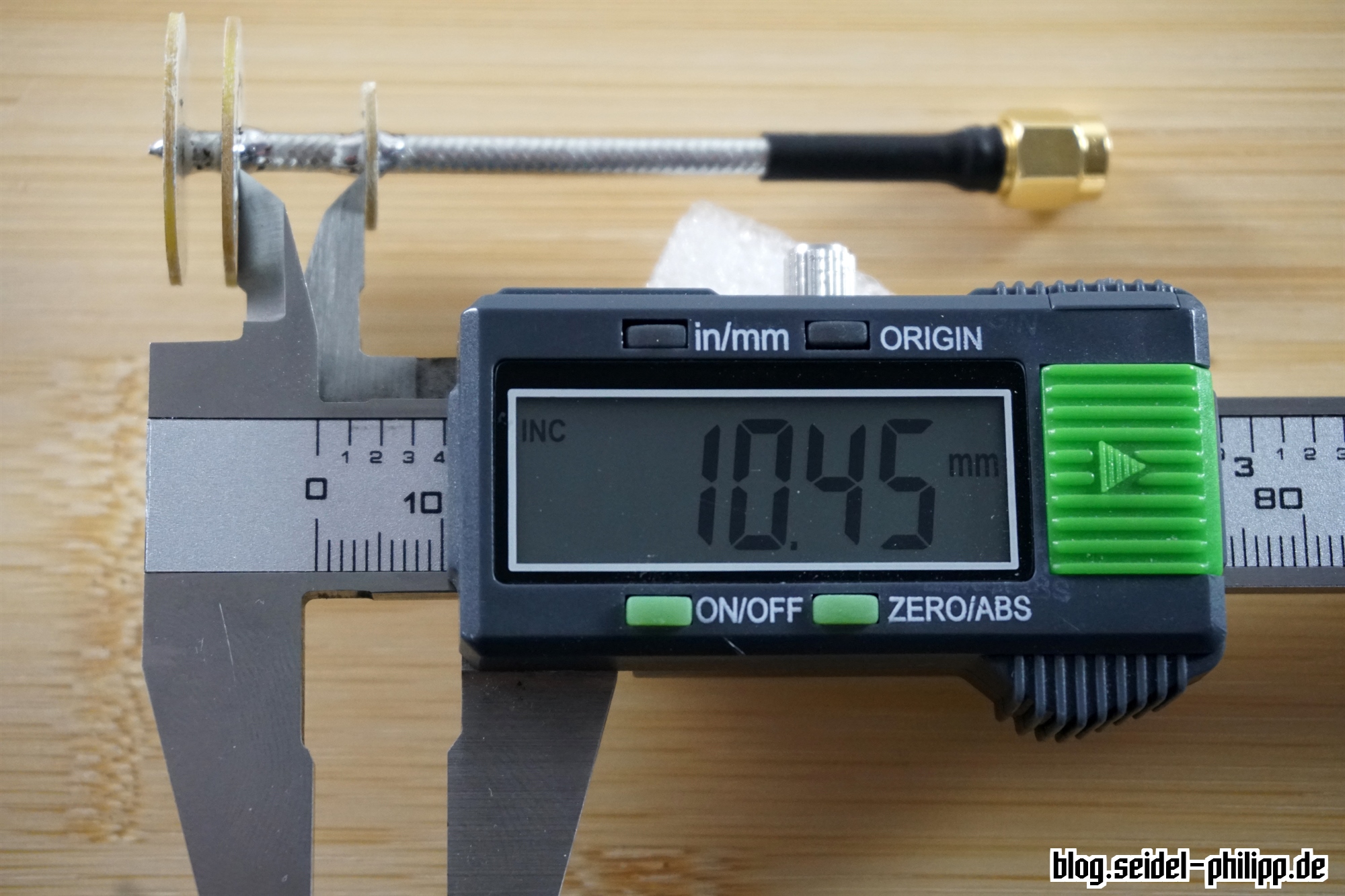
Dimensional inspection
Of course, you do not always have to carry out a measure check, but here you will find the correct spacings.
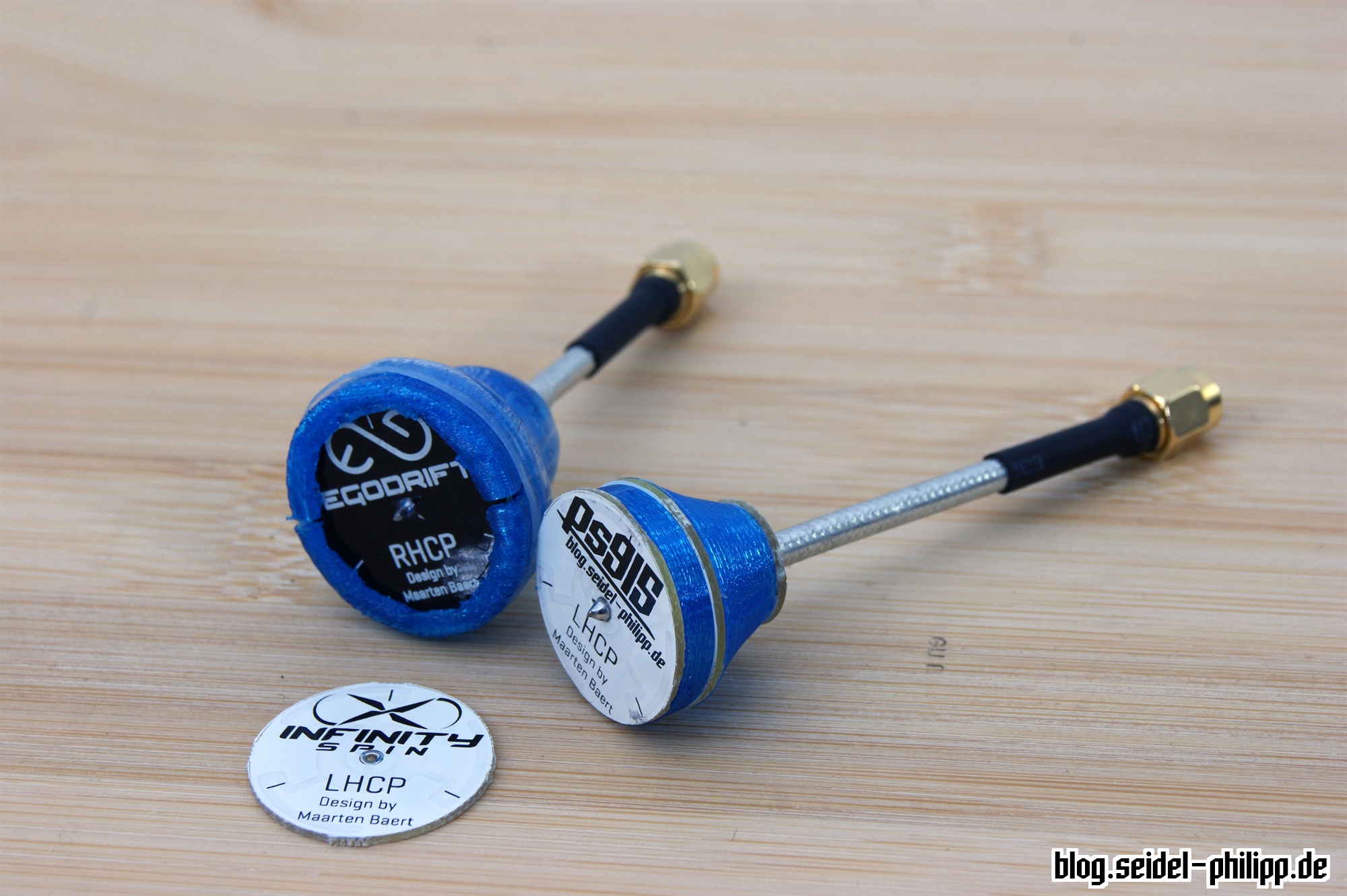
protect your Pagoda FPV Antenna
The Pagoda FPV antenna is undoubtedly one of the best antennas on the market, as long as you protect it adequately. If one fly with the antenna without a protection I guarantee to you that after the first impact the boards are no longer aligned parallel to each other which can influence the signal quality strongly. You must protect your antenna adequately. Currently, I am working on various ways to protect the antenna.
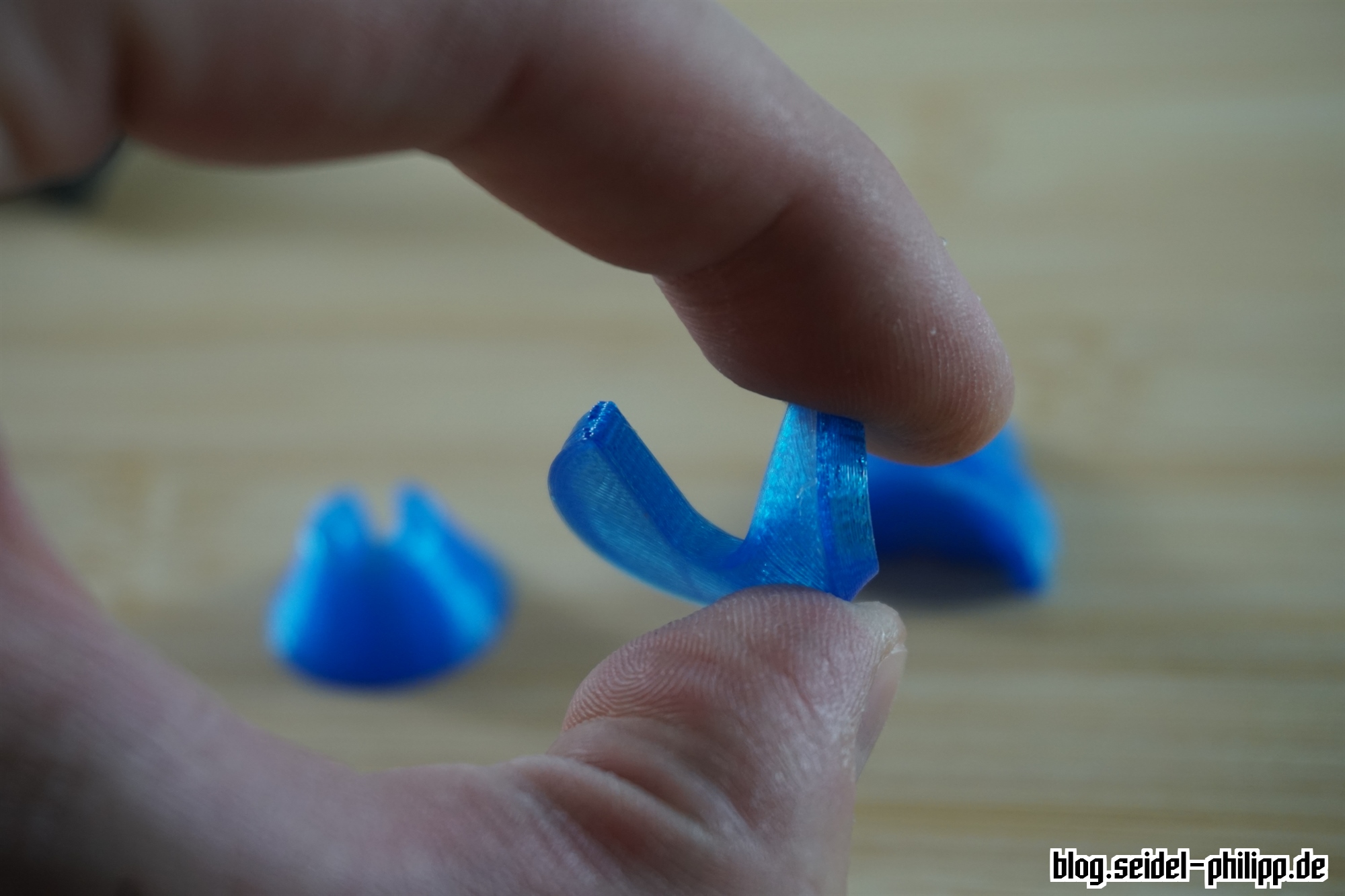
3D printed parts variant 1
At the Intermodellbau fair in Dortmund, fpv24.com was so nice and I printed a lot of these „antenna protection parts„. Thanks again guys!
The material is TPU SainSmart, a flexible filament for 3D printing. After placing the parts around the antenne a transparent shrink tube comes over the antenna to keep everything together.


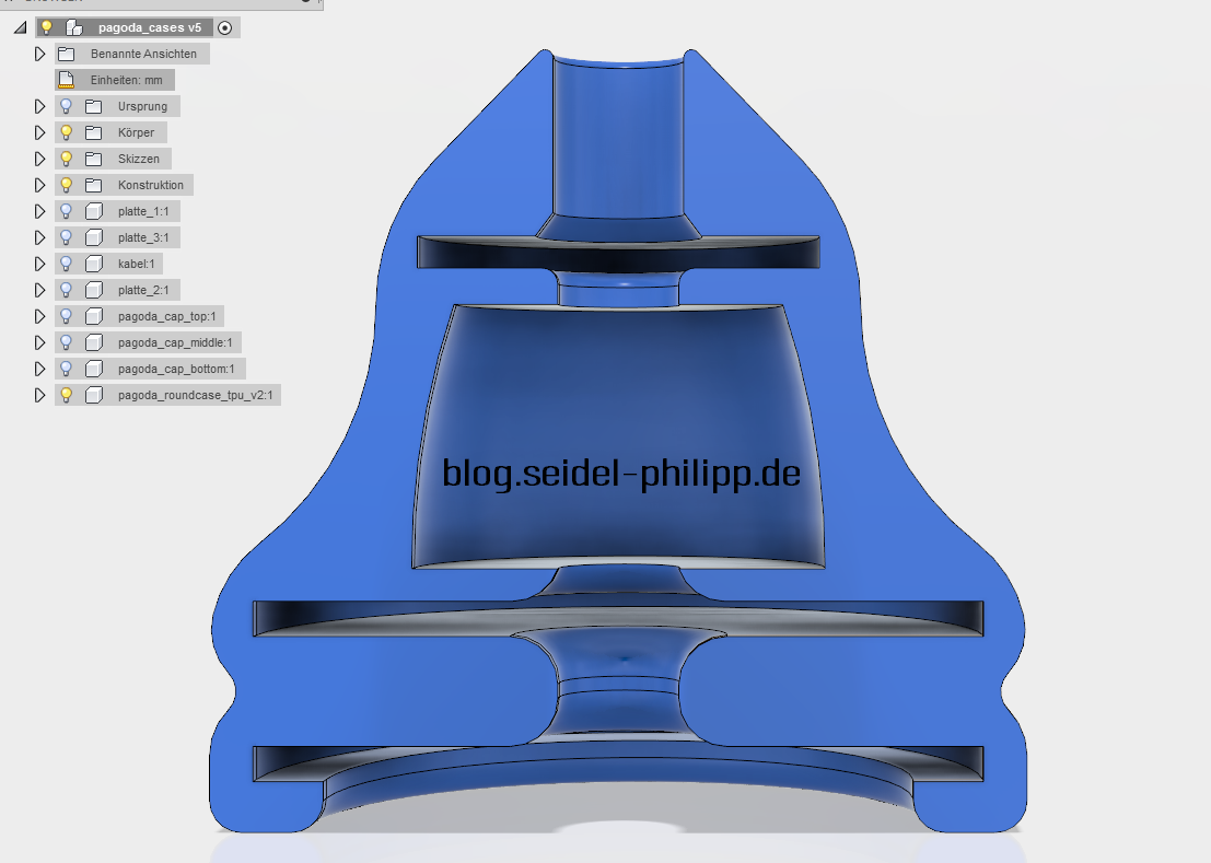
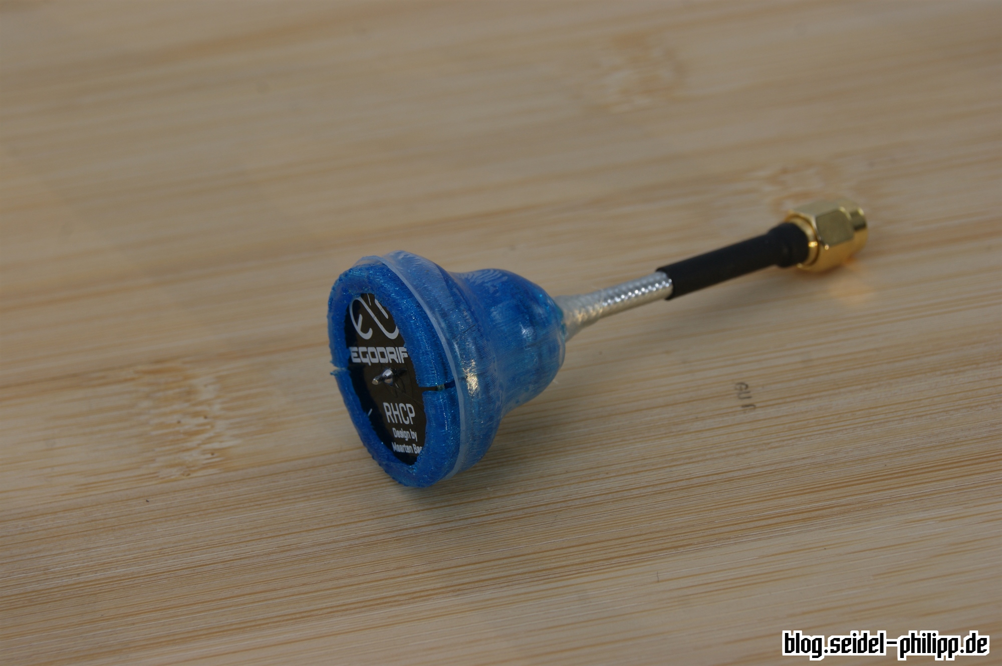
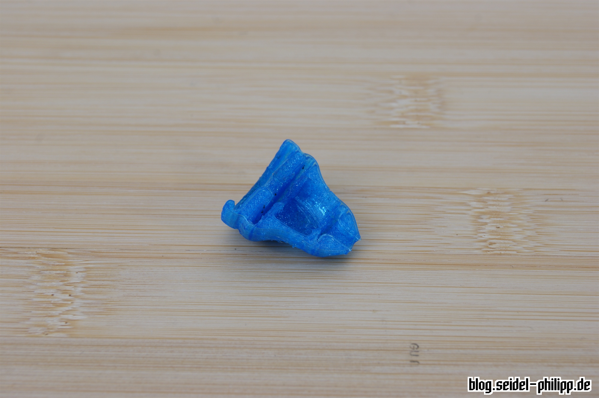
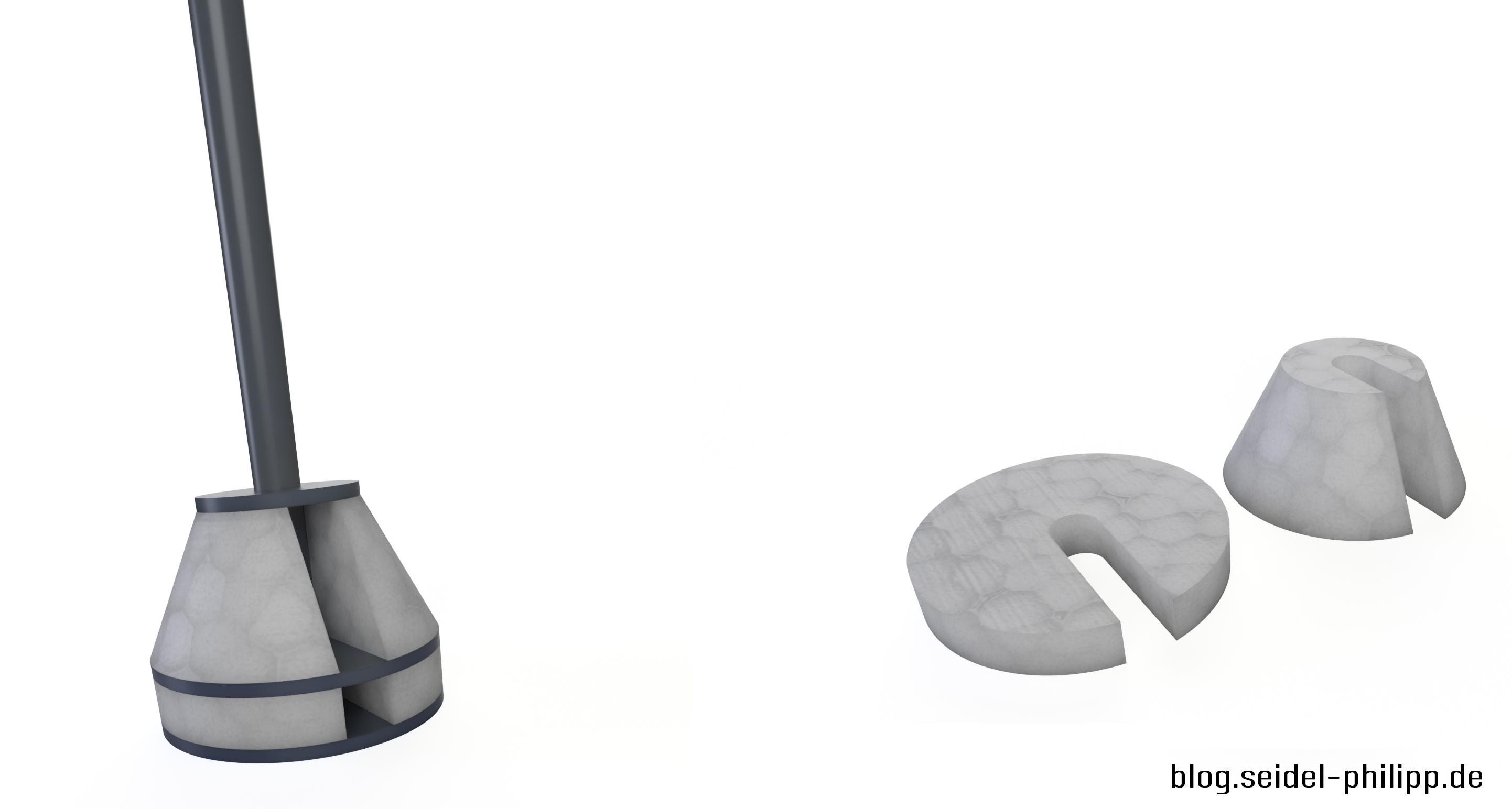
3D printed parts variant 2
I have designed another protective cover [DOWNLOAD] with my new favorite CAD program Fusion 360 which is also printed out of TPU SainSmart material. Disadvantage of this variant is in any case the additional weight. Advantage is clearly the protection of the antenna. It should survive some hard impacts.

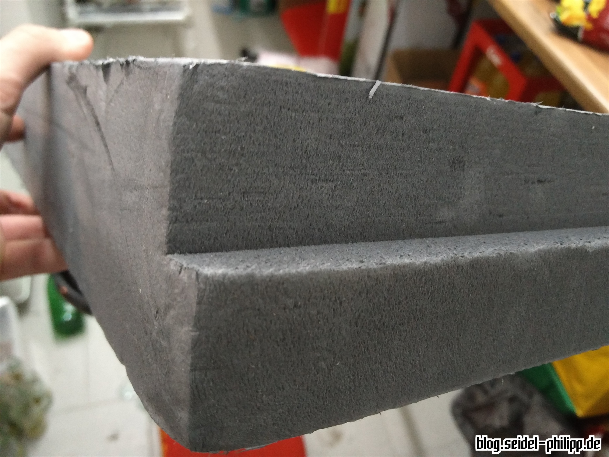
Foam
Polystyrene is a good alternative. It should not affect the signal quality as much and it is still also very light and stable.
It is somewhat difficult to cut the right parts for the antenna. The best solution is to think of the parts by CNC milling machine.
Klaus does not know anything about it yet, but I think he’s going to do something for me again. Stay tuned.

Hey, thanks for these extremely useful writeups! Are the design for your CNC’d construction jig online somewhere?
Hi,
Wo kann man die stl files der ersten Protector Variante herunter laden?
Danke
Hier: http://www.thingiverse.com/thing:2134929 =)