
Flyduino KISS CompactCTRL CC – Anschlussplan / Connection Plan
I created this high resolution connection plan for the Flyduino KISS CompactCTRL CC flight controller, also known as KISS AIOv2
This connection plan will be constantly updated.
Please always link to the original image (3000px × 1760px, right click -> save as) so that the latest version is always displayed.
https://blog.seidel-philipp.de/wp-content/uploads/2017/02/Flyduino_KISS_CompactCTRL_CC_Anschlussplan_connection_plan.jpg
Click the image to enlarge
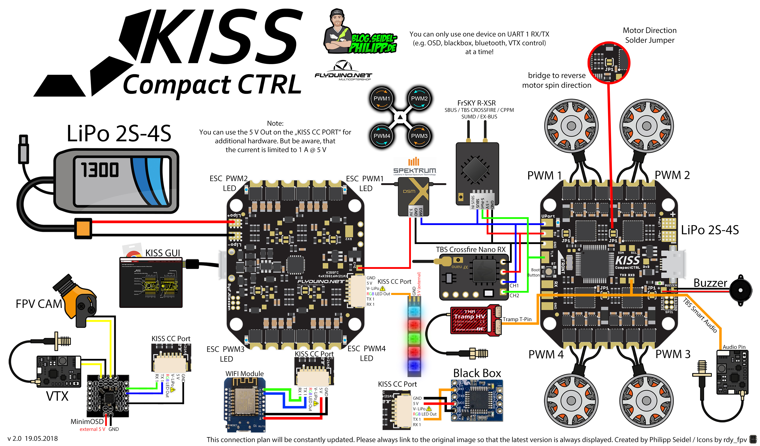
Created by Philipp Seidel / Icons by rdy_fpv

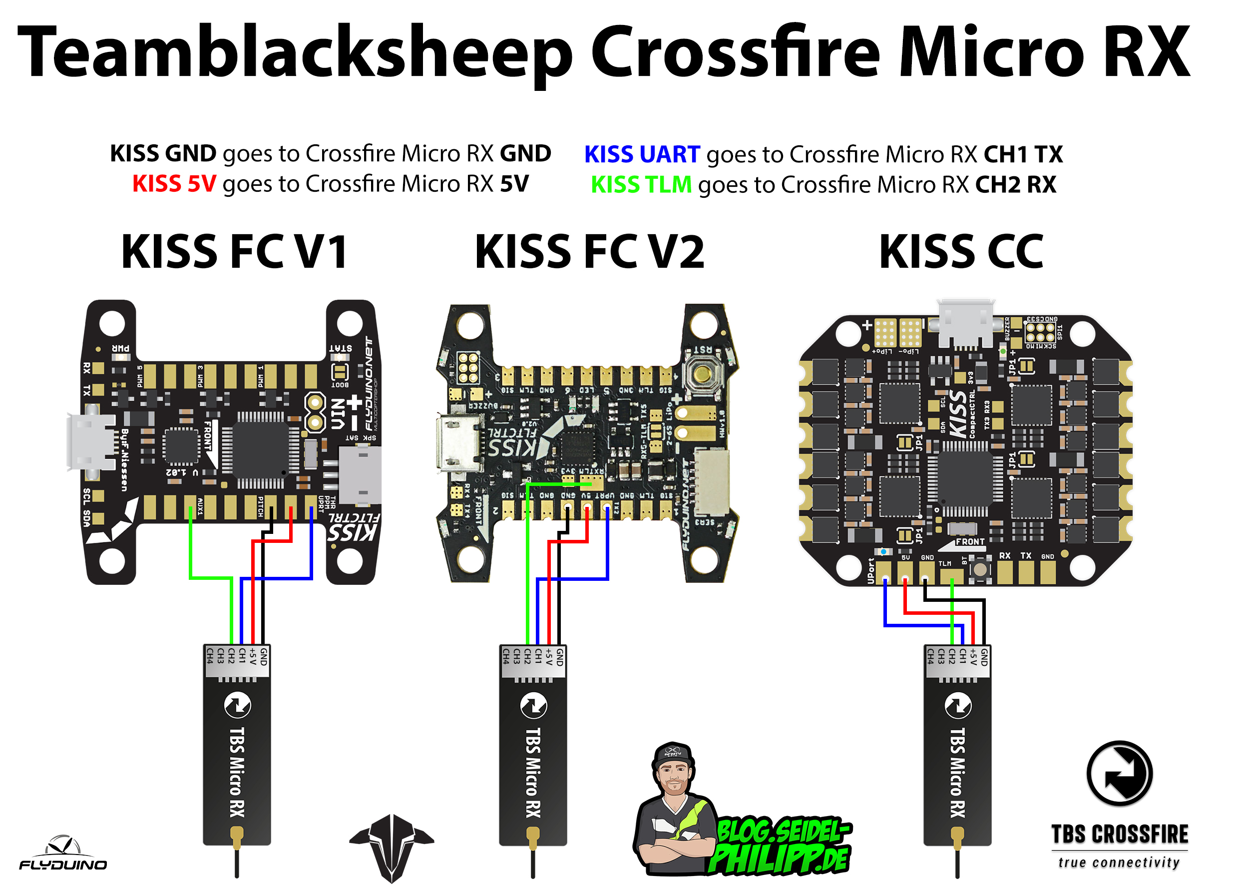
My question is related to the rx hookup on the KISS AIO V2. I am spektrum using their 4649T RX (and have three prior working builds using this rx on the KISS V1 FC). I am aware that it requires 5volts (not 3.3v). I am aware per wiring diagram that the signal wire of this 4649T goes on the same pad used by the FrSky rx’s,,,,the AIO’s Uport pad. However, I have not been able to experience connectivity between my tx and the fc (while in the KISS GUI). The rx is bound to my tx (I receive battery voltage telemetry). And I have tried another 4649 that was off of a working quad. I have the AIO flashed with 1.3-RC34c.hex. The tx mapping is the same as I have used (default settings) on my Spektrum DX8G2 for my three KISS V1FC builds. I have selected the Spektrum RX in the GUI that I have used for the previous builds. I don’t know what else to try because my builds are identical,,,,,with the only exception being that my Spekt RX signal wire is now connected to the Uport pad of the AIO (because there is no Spekt Sat plug). I don’t know if this makes for a different FC circuit pathway that requires some additional setup step that I am unaware of. I have asked a couple of Spekt folks on rcgroups and have gotten no help. I have been on the 4649T rcgroups thread as well as the AIO rcgroups thread and have come up dry. I do have a PM to Flyduino but have not heard back yet (as to whether this hookup change requires an additional step). So, I come to you for help also. I look forward to your thoughts. Thank you
Hey Marty,
that sounds pretty unusual, because i seems you connected it corretcly. Maybe it has something to do with the RX Settings? Maybe it puts out the wrong signal (protocol)? I never ever used Spektrum, so i am not an expert in that.
You may also try the latest KISS CC Firmware which is 1.3RC39b (BETA)!
Report back, if you get in running or not!
Phil
Hi Phil
Bei meinem Kiss CC geht der lipo Anschluss nicht ist das ein bekanntes Problem ?
Über die USB Schnittstelle funktioniert alles normal und kann in der gui geöffnet werden.
Stecker auch schon neu angelötet aber leider keine Besserung.
lg
Kann sein, dass du einen Kurzschluss verursacht hast. Die Pads sind ja sehr nahe beieinander. So habe ich schon mal eine CC zerstört. Ansonsten muss der LiPo Anschluss die FC komplett hochfahren und mit Strom versorgen!
Gruß,
Phil
Kann mann den Buzzler auch alternativ anschliessen ? Minus Pad abgerissen #:-)
He Sergej,
leider nein, denn Buzzer werden über GND geschaltet.
Versuch die Leiterbahn des Pads zu verfolgen und kratze dort frei um es daran zu löten.
Gruß,
Phil
ich habe mir eine KISS CC gegönnt und muss ehrlich sagen, ich finde diese Aktivierung (wenn ich richtig gelesen habe, bei jedem neuen flashen!) absolut nicht in Ordnung !
Gestern die KISS bei mir angekommen und leider dürfte meine eine sein, die nicht in der DB von Flyduino steht – denn sie lässt sich nicht aktivieren. Weder in der Chrome APP noch in der StandAlone Variante. Auch habe ich auf die neuste FW update gemacht, falls das ein Problem sein sollte.
Aber das allerschlimmste wie ich finde: Die mail Adresse auf der flyduino HP info@flyduino.com gibt es gar nicht (554 Sorry, no mailbox here by that name.)
es gibt keinerlei Hinweis auf der Seite bezüglich der Aktivierung
Gerade eine zweite Mail Adresse gesehen info@flyduino.net – anscheinend funktioniert die wenigstens. Mal sehen wann da eine Antwort kommt.
In einem Youtube Video wird gesagt, man soll den Jungs von flyduino in Facebook eine Nachricht schicken – ich habe nur Gott sei Dank kein Facebook
Ich hoffe die Aktivierung funktioniert noch heute, sonst hätte ich eine KISS CC zum Abgeben !
Wenn man schon so eine Sicherung einbaut, sollte man annehmen der Support diesbezüglich wäre ein besserer
Hey Chris,
ja das Thema ist immer noch nicht gegessen. Die Fabrik schafft es nicht die Seriennummern zu sanmeln und in die DB eintragen zu lassen. Frag mich nicht warum. Ich kann deinen Frust echt verstehen! Viel schlimmer wäre es, wenn man auf einem Rennen einen CC tauschen würde und sie nicht aktivierbar ist. Kein deinen Ärger echt verstehen, ging mir auch schon so! 😉
Ich leite deine Beschwerde mal weiter an Flyduino und würde dir auch gerne schnellstmöglich helfen.
Schick mir mal deine CC Seriennummer und den Shop wo du sie gekauft hast, dann leite ich es weiter, ich habe direkt Kontakt zu Flyduino.
Benutze dazu einfach folgendes Formular:
https://blog.seidel-philipp.de/contact/
Besten Grüße,
Phil
PS: Wir bekommen dich schon noch in die Luft!
thx für deine Nachricht – probiere gerade seit ca 15 min dir eine Antwort über das Formular zu schicken – dürfte nur leider im Moment nicht funktionieren
Captcha funktioniert – nach press auf Nachricht senden drehen sich daneben die Pfeile und weiter passiert nichts
Oh man, sorry! Keine Ahnung warum es nicht klappt bei dir! Habe es eben getestet!
habs gerade nochmal probiert – geht nicht (mac – safari)
ich schreibs dir hier – das Formular funktioniert einfach nicht
die Seriennummer lautet: 20383738-42345711-003A002F
habs gekauft bei premium-modellbau.de
Geht klar, ich leite es weiter! =)
Happy Flying!
HEY !!
TOP PHIL !!
ist aktiviert 🙂
Vielen Dank – das ging jetzt echt schnell
Freut mich! =)
Hi, ich würde gern die Telemetrie der ESCs nutzen, welche Jumper müssen dafür gebrückt werden? Kannst du die Bitte noch markieren. Danke und Grüße Mirko
Hallo Mirko,
Die Telemetrie Pads sind intern gebrückt. Du musst nichts weiter machen um die Telemetrie benutzen zu können.
Gruß,
Phil
Hallo, ah ja … das war glaube ich zumindest bei der ersten Version so das man so Jumper brücken mußte.
Grüße und Danke
Mirko
I might add to the last post that no motors meant that my motors wouldn’t spin up. Sorry about that.
Hello,
Thank you for the helpful information on this site. My setup is: AIOv2, FRSKY Ultra Micro receiver, and KDE 1806 motors. I have not connected my camera or TX yet.
I have a question: I just set it up, calibrated the ESC’s setup my Aux 1 switch for arming (low) and set up my receiver with SBUS (non inverted). The radio communicates with the receiver and FC and the motor test showed that communication is good there, but when I plug in my battery to arm the quad I get nothing. The blue light goes on indicating I’ve armed the quad properly but no motors. Any help would be appreciated.
Hi Tim,
what firmware do you use? Can you check if arming is displayed in the Data Output Tab.
The KISS CC must calibrate after plugging the LiPo in. Its important to not move the quad until the calibration is done. If its done, there must be no flashing LED on the KISS CC.
Greets,
Phil
I have my tramp connected to the kiss cc. There is a lot of distortion in the video.. could you tell me how to reduce it? Thx
Hi Tim,
i need a complete list of your parts and also a detailed plan, how you connected everything.
Phil
I placed the camera a bit more to the front, away from the fc.. works great!
Hi,
I fight with my KISS OSD just something about two weeks. What I can’t understand why you take RX1and TX1. I’ve solder the wires on TX RX pads. But I have no signal!?! Is it wrong. I have no 6er JST connector. Can I solder the LED wires somewhere als? And what is the 6 smal holes after the buzzer pads?
rx1 and tx1 is correct. the PDB Port is also rx1 and tx1.
led wires can’t be soldered anywhere else.
Have you configured the serial interface for the OSD?
Phil
Why dont You power micro minimosd and couple of LED’s from Kiss CC 5V 1A? Shoulde be more than enough
Of course, you could do that. But if i do so in the connection plan, some people might add to much devices in the 5V line and the CC will fail. 😉
I will add a note to the picture! =)
Phil
good to know 🙂
is it going to be stable for micro minimosd?
OSD likes to dissapear in some high voltage peaks or hard manouvers if its not powered from clean source.
Better usd an external lc filter for the osd.
I dont own a CC yet, so i cant really say if its working